


Interventional magnetic resonance imaging (MRI) is a growing field, and the strength of MRI guidance for procedures rests fundamentally in the high-contrast imaging of soft tissue structures. Combined with the avoidance of radiation exposure, the potential for functional assessment and the ability to exploit MR signals for calculation of the location of interventional instruments, it is clear that the implementation of interventional MRI will continue to grow. For general cardiac interventions, the visualisation of thin, mobile structures presents particular challenges for MRI guidance. Cardiac electrophysiological (EP) procedures add a further dimension, as the accurate detection of intracardiac electrograms must be performed in a highly active electromagnetic environment. This review focuses on the technical considerations for the performance of EP procedures under MRI guidance (MR-guided EP).
Potential Benefits of MR-guided Electrophysiological Procedures
MRI techniques offer a high soft-tissue contrast-to-noise ratio (CNR) in comparison with that seen with X-ray, computed tomography (CT) and ultrasound. However, the environment can present challenges and is an expensive procedure; therefore, all the benefits of MR-guided EP must be fully considered to justify the additional difficulties and expense. Broadly speaking, these benefits can be divided into three main areas: improved precision of ablation targeting (substrate identification), improved intra-procedural guidance and improved assessment of ablation lesion formation.
Substrate Identification
Both ventricular and atrial arrhythmogenic substrates have been identified on cardiovascular magnetic resonance (CMR) imaging,1,2 and the implementation of CMR data regarding local myocardial characterisation is increasingly used to guide procedures. However, improvements in clinical ablation outcome with the use of CMRderived substrate information have been modest.3 MR-guided EP presents a modality in which CMR-derived substrate could be used more accurately and intuitively to guide procedures.
Ventricular substrate is generally more amenable than atrial to evaluation by CMR owing to increased wall thickness and consequent higher contrast between healthy and pathological tissue. Ventricular tachycardia (VT) in ischaemic cardiomyopathy occurs due to scar-related re-entry and scar can be visualised using late gadolinium enhancement (LGE) techniques.4,5 In particular, the scar border zone has been shown to be critical in the perpetuation of the arrhythmia and its abolition forms the basis of substrate-based VT ablation.6–8 However, caution is required in the direct extrapolation of the imaging to the electrophysiological substrate. Developments in mapping catheter technologies, using smaller and more tightly spaced electrodes, have demonstrated the importance of the fine myocardial architecture in the perpetuation of VT. Conventional LGE resolutions (typically 1.3 x 1.3 mm in-plane) are unlikely to be sufficient,9 and further work is required to establish a firm correlation between CMR-derived scar and critical isthmuses.10
Emerging data also suggest that CMR imaging may be used to guide atrial ablation procedures. Although the atrial wall is thinner, native fibrosis and ablation scar can be identified using primarily threedimensional LGE techniques.2,11 Findings from some studies have been interpreted to suggest that successful ablation of fibrotic regions, distant to the pulmonary veins (PVs), may help improve AF ablation success rates.12 Similarly, atrial re-entrant circuits can be modelled in silico based on atrial scar location and can be used to inform ablation strategies.13 Sites of PV reconnection have been identified using CMR, with successful ablation guided by the CMR-derived substrate,14 but these findings have not been replicated in all studies.15
To date, all studies that have used CMR-derived substrate identification to guide ablation have relied on fusion of the imaging to electroanatomic mapping (EAM) systems.14,16,17 Software adjuncts to conventional EAM packages, such as CARTOSEGTM CT MODULE and CARTOSEGTM MR MODULE (Biosense Webster, Johnson & Johnson), facilitate the registration of imaging data to the EAM-derived anatomy. However, accurate, real-time, registration of the EAM shell and substrate data is crucial and is significantly affected by registration errors (including discrepancies in landmark identification on imaging and electrical criteria), cardiac chamber conformational changes (arising from differing loading conditions and tachyarrhythmias), and translational changes (due to patient movement, cardiac motion and respiratory motion). CMR-derived targets may typically be 2–4 mm wide for VT ablation10,18 and even smaller for atrial ablation.14,19 Small errors in registration mean that either a broad region must be ablated or critical targets left untouched, with consequent impact on safety, time and efficacy.
MR-guided EP can use one of two techniques to overcome such registration errors. The first is the use of image registration within the single imaging modality, rather than trying to match electroanatomic data to imaging data, thus improving matching of landmarks. The second is the use of real-time, or near-real-time, visualisation of substrate, with the imaging performed during the same procedure. Such an approach may improve the outcome of CMR-substrate-guided ablation.
Procedural Guidance
The vast majority of complex ablation procedures are performed using EAM, and procedural guidance is largely reliant on anatomic mapping techniques alone. Fusion with fluoroscopy, using techniques such as CARTOUNIVUTM (Biosense Webster) or intracardiac ultrasound (CARTOSOUNDTM [Biosense Webster]), provides a degree of structural information in addition to that derived from solely EAM. However, the anatomic information and depth of field is inferior to that achieved with CMR imaging. Detailed information on the chamber of interest and the surrounding structures such as oesophagus, coronary arteries and adjacent chambers may assist the performance of many procedures, particularly those for patients with complex congenital heart disease.20 In addition, cardiac motion derived from both respiration and the cardiac cycle can be assessed more accurately using CMR than any other imaging modality. Accurate compensation for this motion may have significant implications for guidance of energy delivery and assessment of ablation efficacy.
Lesion Evaluation
The failure to create durable transmural lesions has been held largely responsible for the high recurrence rates following many complex ablations, particularly VT and AF.21,22 CMR may be used to assess acute ablation lesions,19,23,24 but this does not necessarily mandate the performance of the procedure under MR guidance. One approach might be to perform a conventional procedure with immediate evaluation of lesions prior to removal of sheaths. Patients would undergo CMR assessment, then return to the conventional laboratory for ‘top-up’ ablation of inadequate lesions. However, many factors have inhibited such an approach. First and foremost is the absence of a specific and sensitive acute CMR signature of chronic, effective, lesion formation of sufficient precision to guide further ablation.25,26 Ventricular lesion formation is likely to be more amenable to CMR imaging, but investigations into ventricular lesion imaging are sparse in comparison with those assessing acute atrial ablation lesions. Second, intra-procedural CMR imaging requires substantial disruption: all ferromagnetic material must be removed, and almost all EAM equipment is currently incompatible with CMR imaging. Patches, catheters and most long sheaths must be removed, and, therefore, the registration of imaging to EAM for further ablation requires the procedure to restart almost from scratch. Third, few centres have the facility to move patients easily from the EP laboratory to the MR scanner and back again with sufficient sterility and safety.
MR-guided EP has the potential to streamline the process of acute lesion imaging, and can allow real-time lesion formation imaging to be performed (see Figure 1). Immediate imaging presents the opportunity for early repeat ablation and even energy titration. Imaging techniques continue to be developed, but currently no single technique has been demonstrated to be robust enough for clinical implementation. With time, MR-guided EP may present the opportunity for accurate and tailored ablation lesions.
MR Compatibility of Devices
The MR environment presents considerable challenges in terms of design and use of conventional procedural equipment. Interventional instruments, anaesthetic equipment and monitoring must all be capable of safe and effective operation in the demanding environment. Commercial ablation solutions frequently include non-compatible components, which are not limited to just ferromagnetic materials, and various considerations must be made.
Constraints Associated with the Static Magnetic Field
The presence of ferromagnetic materials is not absolutely contraindicated within the MR environment. However, the use of ferromagnetic materials must be carefully controlled and curtailed as far as possible. Ferromagnetic materials exhibit strong attraction along the line of the magnetic field, and torque to align the object with the field lines. Items that are fixed, such as a stent or iron doping on a catheter tip, will generally remain static within the field. However, for sensitive interventional devices, such as an EP catheter, the forces may be intolerable, and the susceptibility artefact (severely degrading imaging quality) tends to be large.
Constraints Associated with the Rapidly Switching Gradient Fields
Rapidly switching gradient fields have important implications for electrically conductive materials, particularly in the vicinity of highly voltage-sensitive tissue such as myocardium. Modern gradient fields have a steepness of up to 100 mT/m, and a slew rate of up to 200 mT/m/msec.27 The gradient fields cause significant acoustic noise, may induce peripheral nerve stimulation and also cause low-level heating of tissues (low in comparison with radiofrequency [RF]- induced heating). However, a further consideration for MR-guided EP is induction of current and the potential for local cardiac stimulation. Individual catheter channels must be effectively isolated from all other catheter channels to eliminate gradient-induced currents.28
Constraints Associated with the Pulsed Radiofrequency Field
A high-frequency RF field is applied to perform MR imaging, which may induce high-frequency eddy currents in soft tissue and devices producing heat. The heating effect of both the electrical and magnetic components of the RF field is complex to simulate, and is largely dependent on the tuning between the transmit coil and the ‘receiving’ device.27 Multiple tests must be performed to ensure that the worstcase scenario is included, and significant constraints may be placed on transmission lines in particular.29
Device Tracking
Device tracking within the MR environment is of paramount importance, and there are two main methods of localisation: passive and active tracking.
Passive Tracking Sequences
Passive device tracking relies on the identification of the device on an imaging sequence (see Figure 2). Such an approach does not require novel technology to be developed, but it suffers from poor CNR, particularly with thicker imaging slices, and is highly time consuming.
For most passive tracking purposes, a relatively high-speed imaging sequence is required to achieve imaging frame rates of at least 1 Hz. Device identification may be based on a device MR signature that is fundamentally reduced or enhanced for the imaging sequence. Signal reduction is generally achieved through magnetic susceptibility artefact (secondary to the presence of metals) or absence of signal (for non-metallic anhydrous devices). Enhanced signal may be achieved through the use of resonant RF devices30 or filling a device with an enhanced signal source such as a gadolinium-filled tube.
The use of passive tracking sequences generally requires significant input from a skilled MR operator to manipulate the imaging plane to keep the device within slice. This is relatively easily achieved in narrow tubular structures lying within a single plane, such as the aorta, but is much more difficult when there is a greater degree of threedimensional movement. Thicker imaging slices (>10 mm) improve the ability to keep the device within plane, but CNR may be impaired to such a degree that the device may not be identifiable.
There are also two further substantial limitations to passive tracking pertinent to MR-guided EP. The first is the difficulty in tracking more than one device at a time: EP frequently requires multiple diagnostic and ablation catheters, and the narrow MR imaging planes, in contrast to the projection view of fluoroscopy, limits the monitoring of more than one device at a time. The second limitation is the requirement to record the location of devices relative to cardiac structures. Automated image recognition techniques could theoretically be employed when the device tip is in-plane with sufficient CNR, enabling device localisation to be referenced to pre-defined chambers, but such a capability has not yet been demonstrated.
However, passive tracking remains a useful technique, even when actively tracked devices are used (see below). At present, the number of tracked electrodes is highly limited, and therefore there is generally no information on catheter shaft or sheath location. This mirrors the earlier iterations of EAM systems, for which only the location of the catheter tip was visible. Brief runs of passive tracking sequences, preferably in imaging planes defined by the location of the actively tracked catheter tip,31 facilitate the determination of the shaft orientation. Such knowledge may be important in performing more complex catheter manipulations such as those required to reach within a pouch of the Eustachian ridge, or during retrograde access to the left ventricle. Furthermore, active tracking catheters are relatively bulky and expensive, and for simple diagnostic catheters a passive tracking solution may be more appropriate. Therefore, passive tracking remains important even in the era of an active device tracking for MR-guided EP.
Active Tracking Sequences
Active tracking of devices has been achieved using two main techniques. The first exploits the imaging gradient fields to derive device location. Electrical potentials may be induced by the timevariable magnetic fields in a set of miniature coils implanted in the device,32 and this technique has been FDA-cleared for non-cardiac MR-guided interventions (EndoScout® , Robin Medical Inc.). However, it has not been implemented in the cardiac field.
The second technique is that used in MR-guided EP, and this employs a dedicated tracking sequence, detected by micro-coils within the catheter (see Figure 3). The technique was first proposed by Dumoulin et al.33 Small receive coils act to detect a highly localised spatially encoded signal from the surrounding tissue (the coils are insensitive to signal arising more than approximately 1 mm away). High-frequency tracking sequences (>10 Hz) with a high spatial resolution (<1 mm) have been developed and shown to be robust in clinical use.28,34
The signal detected by the micro-receive coils must then be passed from catheter tip to the surface coil port at the scanner itself. As discussed, there are significant concerns regarding RF safety for long transmission lines, while they must remain capable of conducting μV MR-receive signals. Some in vivo studies have used thin, high-resistivity coaxial cable,35 optical fibres36 and modified wires,37 but have not been developed into clinical-grade devices. More recently, an approach based on miniature transformers in the device proved to provide both the required tracking robustness and RF safety,38,39 and further work has resulted in dedicated EP catheters based on this approach.40,41
Implementation Within Electroanatomic Mapping-style Interface
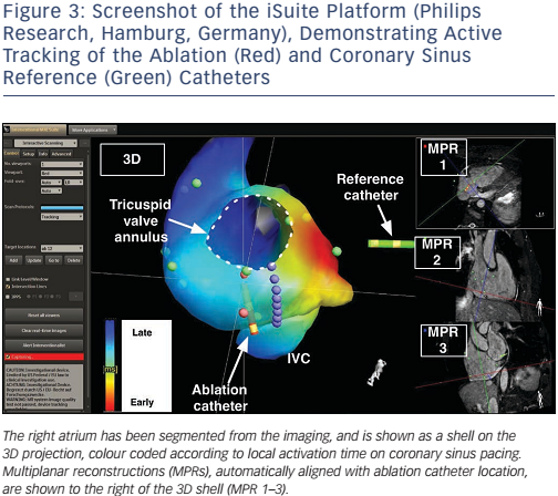
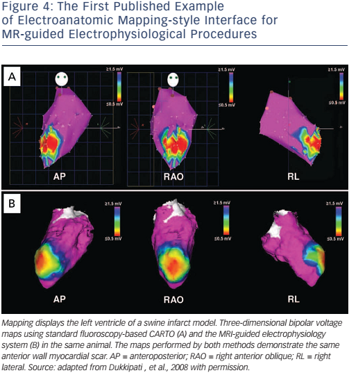
Whether active or passive tracking is used for MR-guided EP interventions, it is necessary to project the location within the context of the cardiac chambers. Most studies have chosen to acquire a threedimensional balanced steady-state free precession (b-SSFP) whole heart volume at the beginning of the procedure, and then to display the location within a segmented chamber of the volume (see Figure 4).28,34,35 Manual or automated chamber segmentations have both been employed to provide an interface that closely mimics the strengths of a clinical EAM system. Passive and active tracking sequences may be interleafed, providing real-time location updates with visualisation of device position and surrounding anatomy, and the passive imaging slice position can be coordinated with catheter tip position.31 An interactive interface may also allow for the rapid switching between several MRI pulse sequences, enabling the visualisation of anatomy with different contrasts (see Figure 3).
An alternative strategy has been proposed by a group from Boston, USA who have modified an impedance-based tracking system, based on EnSite™ Velocity™ (St Jude Medical), and adapted it for use within the MRI environment.42 Using a swine model, they performed diagnostic EP procedures within the MR scanner, using the voltage-based location to guide catheter manipulation. There were considerable technical challenges in terms of optimising the location signal in the MR environment, and tracking performance was impaired by the requirement for blanking of the tracking signal during the gradient field applications. However, the approach has been demonstrated to be feasible and may open the way for a truly hybrid approach, working in both conventional and MR EP laboratories during the same procedure, or for tracking of simpler devices within the MR scanner itself.
Electrogram Fidelity
The detection of cardiac electrical activity is difficult within the MR environment, particularly in the presence of time variable gradient fields and magnetohydrodynamic (MHD) effects. MR-guided EP is currently performed with limited surface electrogram data, typically restricted to four surface electrodes (Expression, Invivo Medical), with marked distortion of many components of the ECG. Identification of the ST-segment and P-wave is often obscured, and many groups are working on improving the electrogram quality and 12-lead ECG solutions.43
There are also challenges related to the detection and transmission of the intra-cardiac electrograms (IEGMs). As for a conventional EP laboratory, IEGMs must be high-pass and low-pass filtered, often with the addition of further notch filters to account for the frequency of mains electricity and other identified sources of noise. Despite filtering, however, electrical noise levels remain high in the MR environment. MHD effects have also been shown to be dependent on catheter orientation, and can result in detected voltages that are higher in late systole than at the R-wave.42 In addition, the IEGM voltage must be transmitted via a high-resistivity, RF-safe transmission line, and IEGM fidelity will need to improve significantly to enable detection of lowamplitude signals such as late diastolic potentials.28
Anaesthesia and Monitoring
MR-guided EP procedures are currently longer than equivalent procedures using conventional guidance, and are performed in a noisy and potentially claustrophobic environment. Therefore, published human studies have been performed under general anaesthesia or deep sedation.28,34,44,45 Maintaining and monitoring anaesthesia in the MR-scanner room differs from conventional anaesthesia in several ways. These include the use of MR-conditional equipment and devices within the room, interference with monitoring (including ECG), and inaccessibility of the patient.
MR-conditional anaesthesia equipment is commercially available, and include the Fabius® MRI (Dräger), which can be operated safely up to the 400 Gauss line. Patient monitoring requires an MR-conditional system, and the most widely employed are those manufactured by Invivo (Expression). These are relatively expensive, but provide a comprehensive range of monitoring, close to that achievable conventionally (CO2, invasive blood pressure, non-invasive blood pressure, saturations, heart rate, and respiratory rate). MR conditionality is generally restricted by power supply transformers, and in the case of the Expression is restricted to 5000 Gauss.
Effective and reliable monitoring is particularly important in the context of a patient who is largely hidden from view within the scanner bore. The airway is vulnerable with no visual confirmation of endotracheal tube position, temperature is often difficult to regulate without conventional warming, and the table is relatively hard, increasing risk to pressure areas. Furthermore, the anaesthetist generally sits within the control room to avoid scanner noise and special consideration is therefore needed for effective communication with the interventional team. All these factors need to be considered carefully in the planning of interventional procedures.
The final consideration is evacuation in the event of emergency, with particular focus on life-threatening arrhythmias. There is currently no commercial MR-conditional defibrillator available, although there is ongoing work to develop such capability.46 Therefore, robust protocols and training must be in place for evacuation of the patient to a safe zone for medical resuscitation if required.
Brief History of MR-guided Electrophysiological Procedures
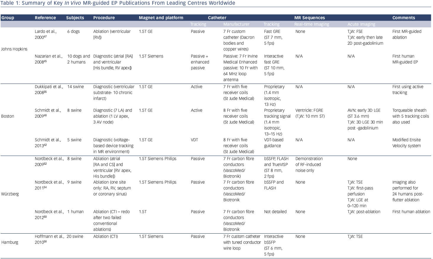
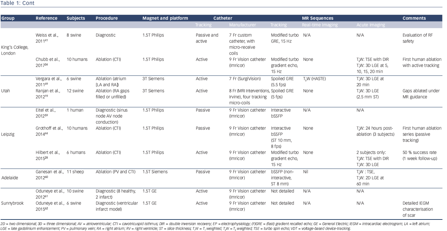
Table 1 summarises the key publications from the leading groups worldwide working in MR-guided EP. Pioneering studies by the group at John Hopkins University, led by Henry Halperin, established the benchmarks for the field in 2000 and highlighted the technical challenges that remained.47 Active tracking for EP procedures was established in vivo in 2008 by the Boston group, with the creation of an early EAM-style interface that has become the standard for ongoing MR-guided EP work (see Figure 4).35 They went on to investigate real time visualisation of lesion formation,48 a challenging area that has also been investigated by a group in Utah, USA.49
Translation to clinical implementation has been difficult. The burden of proof of safety for human use for every item of equipment is high, and Nazarian et al. published the first report of a diagnostic MR-guided EP study in humans in 2008.45 MR-compatible catheters were created using a polyether block amide plastic body, copper wires and platinum electrodes. A susceptibility artefact approximately 1 mm around the catheter was used for passive position identification on two-dimensional fast gradient echo sequences, and it was possible to perform catheter mapping of a previously ablated cavo-tricuspid isthmus (CTI). Catheter position was confirmed through a combination of real-time MRI guidance and intracardiac electrograms. Electrical interference from gradient switching was suppressed through the use of 30–300 Hz bandpass filtering, allowing even the low-voltage His bundle electrogram to be identified. However, the procedures were lengthy and the studies were discontinued.
The first human ablation procedure was performed by a group from Würzberg, Germany in 2012, completing a CTI ablation following two previous failed conventional procedures.50 A group from Leipzig, Germany went on to perform further CTI ablation procedures using the Imricor Vision catheter (Imricor Inc.) under passive guidance.44 Ten patients underwent MR-guided ablation, but it was only possible to achieve conduction block in one of the 10 patients using MR-guided ablation alone. The nine remaining patients required further ablation under conventional fluoroscopic guidance, and one of the main issues identified was the work-flow difficulty with passive tracking of the catheter. The first human study to use active catheter tracking was performed in 2014 in London, UK and the technology has also been demonstrated by the group in Leipzig.28,34
Radiofrequency Ablation Within the MR Environmentz
RF ablation within the MR environment has been demonstrated to be safe and feasible under the correct precautions. RF ablation of liver lesions, solid tumours in the lung, kidney and symptomatic bone tumours have all been described.51 The frequency of RF ablation energy is approximately 350 kHz, which is significantly lower than the Larmor frequency in clinical scanners (64–138 MHz). However, the rectangularpulsed waveform of the ablation energy contains higher harmonics that have been shown to destroy imaging.47,52 Low-pass filtering is therefore required to maintain imaging quality, and this enables the potential for live imaging of lesion formation.
Real-time Lesion Imaging
Only a small body of literature has demonstrated real-time MR imaging of cardiac lesion formation. Clearly, it can only be performed for MR-guided EP procedures, and relatively few studies have focused on this aspect of research (see Table 1). Real-time lesion imaging is attractive as it could provide a means to titrate energy delivery, potentially decreasing procedural time, increasing efficacy and reducing procedural risk.
Steiner et al. first demonstrated the technical feasibility of realtime in vivo MRI of RF lesion formation for a swine paraspinal muscle ablation.53 However, it was not until 2009 that Schmidt et al. demonstrated real-time imaging of a ventricular RF lesion, using a fast T 1-weighted gradient recalled echo sequence (ECG-gated, 10 mm slice thickness, one slice per 2 second acquisition).48 In the report, details regarding the results of imaging are limited to only presentation within a figure and were not quantified, but they appeared promising.
Vergara et al. published a more detailed study in 2011, using T2-weighted imaging (T2W-HASTE) to detect real-time lesion formation visualisation, again in a swine model.49 This was followed by a three-dimensional late gadolinium enhancement acquisition at 20 min. However, only 30 % of lesions could be visualised during ablation. Where lesion visualisation occurred, changes were identified within 10-15 sec of commencement of energy delivery, but lesion size was over-estimated on imaging performed at later time points during the ablation (45–60 sec after commencement). This finding is in keeping with other assessments of acute T2-weighted imaging25,26 and such early distant changes means that it is unlikely that T2-weighted imaging will prove to be specific for chronic lesion formation.
An alternative strategy for real-time imaging is to leave the catheter in place and perform ‘hyper-acute’ imaging of the ablation lesion, seconds after the completion of energy delivery. The susceptibility artefact of the MR-compatible catheters is generally small, facilitating such an approach; this would enable immediate reapplication of energy if the lesion were judged inadequate.48,54
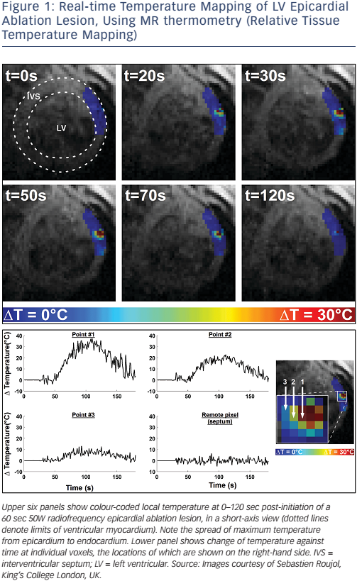
In the longer term, it is likely that real-time lesion formation imaging will rely on more novel sequences, and exploit acute physiological changes such as MR thermometry (see Figure 1).
Acute Lesion Imaging (<4 Hours)
There is a great deal more evidence for acute imaging of ablation lesions, but the sensitivity and specificity of acute lesion imaging for prediction of chronic lesion formation remains controversial. Furthermore, much of the data on human ablation relates to imaging at 24 hours post ablation, which is not a clinically useful time interval. Imaging needs to be performed at the same procedure to guide further ablation, and, therefore, a maximum time interval of approximately 4 hours post ablation is considered applicable for intra-procedural acute imaging.
In animal models, it has long been established that ventricular and atrial lesions can be visualised immediately following ablation.47,55 Detailed delineation of the pharmacokinetics of gadolinium within acute RF injury lesions24 has been performed, and has been correlated with nonenhanced sequences such as T2-weighted, turbo-spin echo techniques.54 First-pass hypoenhancement and native T1 sequences have been particularly promising, and Vijayakumar et al. have demonstrated the use of non-contrast T1-weighted imaging in the acute identification of chronic lesions in a canine model of ventricular scar.56
Non-contrast agent-based imaging techniques are particularly attractive as they can be repeated multiple times. Furthermore, the potential for toxicity related to the interaction of RF energy and gadoliniumbased contrast agents is undetermined, although gadolinium has been shown to augment lesion formation.57 Celik et al. performed a detailed study of the characterisation of acute RF lesions using native contrast, performing imaging of left ventricular lesions within 60 min of ablation in 13 pigs.23 They concluded that it was the higher ferric iron concentration in lesion core that caused a shortening of T1-relaxation time, and that this was best exploited using an inversion recovery SSFP sequence. Implementation and clinical validation in humans remains to be established.
The Financial Cost of MR-guided Electrophysiological Procedures
There are currently no comprehensive commercial solutions available on the open market for MR-EP, and therefore it is not yet possible to determine cost-effectiveness. Furthermore, while technological developments are still required to leverage the full potential of MR-EP, such as detailed substrate evaluation and real-time lesion assessment, it is clear that MR-EP rests largely in the research field. In the longer term, the cost of MR-EP has the potential to trend towards that of conventional EAM-guided EP procedures. The cost calculations for the use of the main hardware item, the MRI scanner, vary widely between centres, and at our institution is approximately twice that of the operational EP catheter laboratory. Selected disposable items are not required for MR-guided ablation procedures, such as EAM patches, and may offset that cost by a small degree, particularly if fewer mapping and ablation catheters are required. However, the fundamental calculation of cost-effectiveness will rely on procedural efficacy and whether time is saved through the direct application of imaging; this can only be answered through adoption and development of the techniques.
Five-year View
MR-guided EP will continue to evolve, and several investigational products are now close to achieving CE mark status. The commercial availability of an MR-compatible ablation catheter, digital amplifier stimulator and image guidance platform will make the technology more widely available and should greatly accelerate developments in the field. Longer-term mainstream adoption of MR-guidance for EP is dependent on substantial investment and co-operation of imaging and EP partners, and will also require the training of teams and individuals with crossover skills in both EP and MRI. However, if improved procedural outcomes can be demonstrated, then the technology has the potential to expand rapidly.
Conclusion
MR-guided EP remains a research field in relative infancy, and advances have been slowed by the considerable technical challenges that it presents. The potential benefits, however, are substantial and research into this exciting field will accelerate greatly with the development of a robust, clinically approved, MR-guided EP system.