


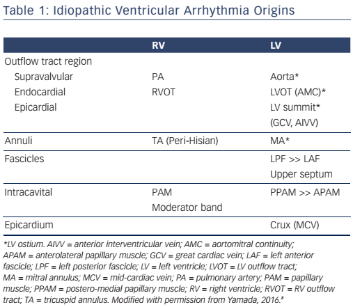
Idiopathic ventricular arrhythmias (IVAs) usually originate from the specific anatomical structures. For the past decade, major IVA origins from both endocardial and epicardial sites have been increasingly recognised (see Table 1).1–3 Catheter ablation of IVAs is usually safe and highly successful, but can sometimes be challenging because of the anatomical obstacles. Therefore, understanding the relevant anatomy is important to achieve a safe and successful catheter ablation of IVAs. This review describes the anatomical considerations in catheter ablation of IVAs.
Idiopathic Ventricular Arrhythmia Origins Relevant to the Anatomy
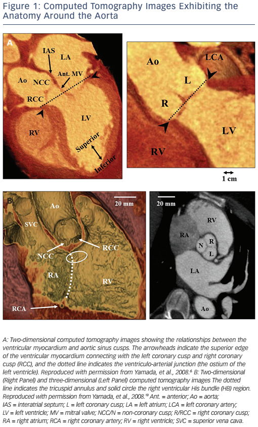
The most common site of IVA origins is the ventricular outflow tract.3,4 IVAs originate more often from the right ventricular outflow tract (RVOT) than from the left ventricular outflow tract (LVOT). In the RVOT, the septum is a more common site of IVA origins than the free wall. The most common site of IVA origins in the LVOT is the aortic root followed by the sites underneath the aortic coronary cusps (see Figure 1A).5,6 Especially, the site underneath the left coronary cusp (LCC) is termed the aortomitral continuity (AMC). The mitral annulus is also one of the major sites of IVA origins.7,8 The anteromedial aspect of the mitral annulus continues to join the AMC. Anatomically, the aortic and mitral valves are in direct apposition and attach to the elliptical opening at the base of the left ventricle (LV) known as the LV ostium (see Figure 1A).9,10 As there is no myocardium between the aortic and mitral valves (fibrous trigone), LV IVAs usually originate from along the LV ostium. The LV myocardium comes in direct contact with the aorta at the base of the aortic coronary cusps (see Figure 1A).
When IVAs arise from the most superior portion of the LV ostium (the aortic sinuses of Valsalva), they can be ablated at the base of the aortic coronary cusps. Some IVAs can be ablated from the junction (commissure) between the left and right coronary cusps (L-RCC).11 In these IVAs, catheter ablation from underneath the aortic coronary cusps is often required for their elimination. Anatomically, the superior end of the LV myocardium makes a semi-circular attachment to the aortic root at the bottom of the right and left coronary cusps. However, because of the semilunar nature of the attachments of the aortic coronary cusps, the superior end of the LV myocardium is located underneath the aortic valves at the L-RCC (see Figure 1A). Therefore, IVAs that can be ablated at the L-RCC should be classified into the same group as the IVAs that can be ablated within the aortic coronary cusps. In this setting, these IVAs may be defined as IVAs arising from the aortic root.6 IVAs can rarely be ablated from within the non-coronary cusp (NCC) of the aorta.6,12,13 Spatially, the aortic root occupies a central location within the heart, with the NCC anterior and superior to the paraseptal region of the atria close to the superior atrioventricular (AV) junctions (see Figure 1B).10 In normal human hearts, the NCC is adjacent to the atrial myocardium on the epicardial aspect and the NCC does not usually come into direct contact with the ventricular myocardium (see Figure 1B). Indeed, atrial tachycardias that can be ablated from within the NCC are far more common than ventricular arrhythmias (VAs). However, the clinical observation that a non-coronary sinus of Valsalva aneurysm can rupture into the right ventricle (RV) as well as the right atrium, supports the assumption that the NCC may be attached to the ventricular myocardium from which IVAs can arise. 12 IVAs can arise from the pulmonary artery with a ventricular myocardial extension from the RVOT.14 It should be noted that ventricular myocardial extensions never occur in the aorta.10
IVAs can originate from the AV annuli including the mitral annulus7,8 and tricuspid annulus.15 Mitral annular IVAs can originate from any regions along the mitral annulus, but the anterolateral and postero-septal aspects of the mitral annulus are the most common and second most common sites of mitral annular IVA origins, respectively.7,8 Tricuspid annular IVAs can originate from any region along the tricuspid annulus, but more often originate from the septal aspect, especially in the anteroseptal or para-Hisian region than the free wall.15
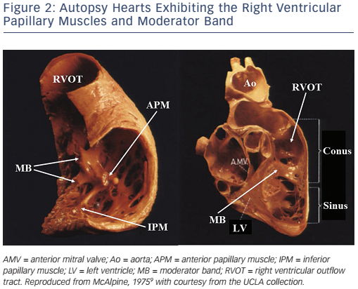
IVAs can arise from intracavitary structures including the papillary muscles16–20 and moderator band.21 LV papillary muscle IVAs are known to arise more commonly from the postero-medial papillary muscle than the anterolateral papillary muscle.18 The sites of the papillary muscle IVA origins are limited to the base of the papillary muscles. IVAs can rarely originate from the papillary muscles in the RV (see Figure 2).20 IVAs can arise from all three RV papillary muscles, though half arise from the septal papillary muscle.20 Although more rare, the moderator band can be a source of IVAs including premature ventricular contractions (PVCs), ventricular tachycardias (VTs) and ventricular fibrillation.21 Anatomically, the moderator band is considered to be a part of the septomarginal trabeculation, crossing from the septum to the RV free wall and supporting the anterior papillary muscle of the tricuspid valve (see Figure 2).21
IVAs can arise from the Purkinje network, most commonly from the left posterior fascicle followed by the anterior and septal fascicles.19,22,23 The anterior fascicle runs along the mitral annulus, and the peripheral Purkinje network extends to the surface of the papillary muscles and moderator band. Therefore, these IVAs have to be differentiated from IVAs originating from the papillary muscles, moderator band and AV annuli.
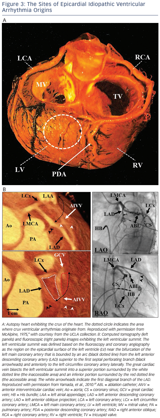
IVAs usually arise from the endocardium, but can also arise from the epicardium,24 and rarely from the intramural site.25 There are two major sites of epicardial IVA origins such as the crux of the heart26 and LV summit.27 Anatomically, the crux of the heart is formed by the junction of the AV groove and posterior interventricular groove, and corresponds roughly to the junction of the middle cardiac vein and coronary sinus (CS), near the origin of the posterior descending coronary artery (see Figure 3A).26 A region of the LV epicardial surface that occupies the most superior portion of the LV has been termed the LV summit by McAlpine (see Figure 3B).9,27 The LV summit is a triangular region bounded by the left anterior descending coronary artery anteriorly and left circumflex coronary artery posteriorly, and an imaginary arch sweeping from the first septal coronary artery across the lateral LV epicardium to the left AV groove. The great cardiac vein (GCV), which continues to become the anterior interventricular cardiac vein (AIVV) bisects the LV summit. The portion of the LV summit lateral to the GCV is accessible to epicardial catheter ablation (the accessible area). The region of the LV summit superior to the GCV is generally inaccessible to catheter ablation due to the close proximity of the coronary arteries and the thick layer of epicardial fat that overlies the proximal portion of these vessels (the inaccessible area).27
Mapping and Catheter Ablation of the Specific Idiopathic Ventricular Arrhythmia Origins
Ventricular Outflow Tracts and Aortic Root
Anatomically, the RVOT and LVOT are located next to each other, and it is often difficult to predict IVA origins from the RVOT or LVOT by the electrocardiograms prior to the procedure. Therefore, mapping in the RV should be first performed in all patients with IVAs exhibiting a left bundle branch block QRS morphology. Activation mapping seeking the earliest bipolar activity and/or a local unipolar QS pattern during IVAs is most reliable for identifying a site of an IVA origin. Pace mapping is especially helpful for RVOT IVAs,1,2 but is less helpful for aortic root IVAs because pacing within the aortic coronary cusps may not exactly reproduce the QRS morphology of the IVAs due to preferential conduction across the ventricular septum28 or the inability to obtain myocardial capture despite the use of a high pacing current. When there are no suitable sites for ablation in the RV or when RV catheter ablation is unsuccessful, mapping in the aortic coronary cusps and LVOT should follow. As the posterior portion of the RVOT is in close apposition to the LV near the aortic root, when catheter ablation has not been successful in the LVOT, the RV should be carefully remapped before determining that an epicardial approach is required.
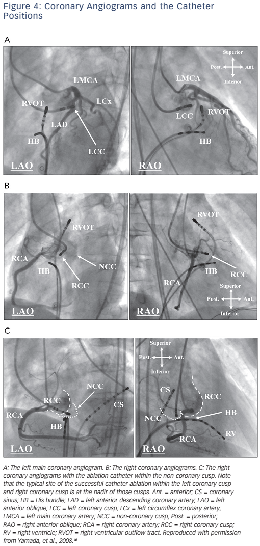
Before mapping and catheter ablation within the aortic coronary cusps, selective angiography of the coronary artery and aorta should be performed to carefully determine the coronary artery ostia in the aortic coronary cusps, to precisely define the location of the ablation catheter and to avoid arterial injury (see Figure 4).2,6,10 Calcifications of the coronary arteries in older patients may also facilitate delineation of the ostia of the coronary arteries. The three aortic coronary cusps can be readily identified during biplane aortography or coronary angiography. The LCC is most easily identified in the left anterior oblique (LAO) projection where this cusp is on the far lateral aspect of the aortic root, leftward and superior to the His bundle (HB) catheter (see Figure 4A). The RCC usually requires coronary angiography in both the right anterior oblique (RAO) and LAO projections for an accurate identification of the cusp relative to the right coronary artery (RCA) ostium (see Figure 4B). In the RAO projection, the ablation catheter is typically located anterior and inferior to the RCA ostium. In the LAO projection, the typical ablation site is more leftward in the RCC than the RCA ostium. The NCC is readily identified as the most inferior of the three cusps and by its close relation to the HB catheter (see Figure 4C). In the RAO projection, a catheter in the NCC is posterior and inferior to the RCA ostium, just above the HB catheter. In the LAO projection, the NCC is just superior to the HB catheter, well posterior to the RCA ostium. As the NCC overlies the atrial septum, the amplitude of an atrial electrogram is usually larger than that of the ventricular electrogram within the NCC.
A ventricular pre-potential preceding the QRS onset is often recorded at the aortic root during IVAs and it may predict a successful ablation site.6,15 Pacing within the aortic coronary cusps often exhibits a long stimulus to QRS interval (more likely in the LCC than the RCC) whereas pacing below the aortic valves gives no latency between the pacing stimulus and QRS onset.6,10
In the aortic coronary cusps, radiofrequency catheter ablation (RFCA) is applied under continuous fluoroscopic observation with an angiographic catheter positioned within the ostium of the coronary artery. The outline of the aortic coronary cusps and flow in the coronary artery are intermittently observed by hand injections of contrast. RFCA should be avoided within 5 mm of the coronary artery. There is a potential risk of aortic insufficiency.
Purkinje System
IVAs can originate from the Purkinje system with a focal or reentrant mechanism. When IVAs originate from the Purkinje network, a Purkinje potential always precedes the QRS onset during IVAs, and is also recorded during sinus rhythm at the successful ablation sites. Left fascicular VTs occur with a reentrant mechanism involving the left anterior or posterior fascicle (posterior fascicle is more prevalent).22,23 It has been suggested that Purkinje tissue forms an important part of this reentrant VT circuit.22,23 Based on this anatomical and electrophysiological background, mapping for ablation is performed around the anatomical location of the involved fascicle seeking a discrete Purkinje potential that precedes the QRS complex during VT.22,23 Ablation at a basal site may be complicated with left bundle branch block. Therefore, catheter ablation should start from an apical site and shift toward a basal site until successful ablation is achieved. Catheter-induced trauma to the substrate may sometimes render the IVAs non-inducible, resulting in ablation failure.
Left fascicular VTs are frequently not inducible or non-sustained at the time of the planned catheter ablation. In such a case, mapping and ablation targeting retrograde Purkinje potentials recorded at the mid-inferior septum during sinus rhythm may be an alternative approach.29 A linear RFCA strategy guided by the presence of Purkinje potentials during sinus rhythm, with pace mapping as an additional guide may also be effective.30 A linear radiofrequency lesion set is placed perpendicular to the long axis of the LV, approximately midway from the base to the apex in the region of the mid to mid-inferior septum. This approach may be complicated with left posterior fascicular block.
Papillary Muscles
RFCA of papillary muscle IVAs is very challenging as compared with that of the other IVAs, probably because of the deep location of the origin relative to the endocardial surface of the papillary muscles, and the difficulty in maintaining stable contact of the catheter tip at the papillary muscles with the vigorous motion associated with normal contraction of the papillary muscles.16–18 As a result of a deep origin of the papillary muscle IVAs, suppression of papillary muscle IVAs by a mechanical compression is rare, and instead, touching of a mapping catheter on the papillary muscles easily induces PVCs, which preclude activation mapping. A retrograde transaortic approach is usually used for mapping and catheter ablation of LV papillary muscle IVAs. A transseptal approach may be used to improve the contact and stability of the ablation catheter on the postero-medial papillary muscle during mapping of LV postero-medial papillary muscle IVAs,8 although that is not an option for mapping of LV anterolateral papillary muscle IVAs.
For identifying the papillary muscle IVA origin, activation mapping is the most reliable method. Although pace mapping usually provides helpful clues in IVAs, a discrete radiofrequency lesion at the site with an excellent pace map is likely to fail to eliminate the papillary muscle IVAs. Instead, there is often a change in the QRS morphology after a radiofrequency application, probably because the site of the papillary muscle IVA origin may be located away from the breakout site, which can be recognised as the site with the best pace map. When the patient does not have an excellent pace map, further radiofrequency lesions will be required to completely eliminate the papillary muscle IVAs as compared with that in the patients with an excellent pace map because there should be no discrete breakout sites from a deeper IVA origin.
The creation of a deep radiofrequency lesion may be necessary for the long term success of the catheter ablation of papillary muscle IVAs because of the distance between the papillary muscle IVA origin and endocardial surface. Therefore, the use of high radiofrequency power settings delivered from an irrigated tip ablation catheter is strongly recommended in the catheter ablation of papillary muscle IVAs. Understanding the fluoroscopic location of the papillary muscles with an LV electrogram is helpful, but an intensive monitoring with transthoracic and intracardiac echocardiography and/or a three-dimensional mapping system should be used as a guide for mapping.16–18,31
Patients with papillary muscle IVAs often exhibit variable QRS morphologies spontaneously and/or after the initial ablation lesions.18 The altered QRS morphologies of papillary muscle IVAs after the ablation may guide the following mapping and catheter ablation. Understanding the relationship between the changes in the QRS morphology and a shift in the breakout site to the opposite side of the papillary muscle may be helpful for determining the next target of the mapping and ablation. In these patients, radiofrequency lesions on both sides of the papillary muscles are often required to eliminate all variations in the QRS morphology. These differences in the QRS morphologies are compatible with the differences in the direction of the vector of the propagating wavefront from the successful ablation sites on both sides of the papillary muscles and can be reproduced by pacing from those sites. In these patients, a single IVA origin with preferential conduction to multiple exit sites is likely to operate with anisotropic conduction from the anatomic background that the LV papillary muscles are composed of a complex of myocardial strands with some separations between them on the basal and apical sides. Therefore, in some of these patients, radiofrequency lesions at a single site can eliminate all spontaneous QRS morphologies.
A low-amplitude ventricular pre-potential is often recorded at the successful ablation site. The mechanisms in the papillary muscle IVAs addressed above can also explain the presence of these pre-potentials and the possibility of isolating that pre-potential was demonstrated in one case study.32 Although a ventricular pre-potential is also often recorded at the successful ablation site of IVAs arising from the LV ostium,10 the mechanism of those ventricular pre-potentials is likely to differ between papillary muscle IVAs and LV ostial IVAs. In LV ostial IVAs, the first ventricular potential is a near-field electrogram representing the activation at the site of the IVA origin, while the second ventricular potential is a far-field electrogram representing the activation of the larger myocardial mass around the VA origin. On the other hand, for papillary muscle IVAs, the first ventricular potential is more likely a far-field electrogram representing the activation of the IVA origin deep under the surface of the papillary muscles, while the second ventricular potential is a near-field electrogram representing activation of the surface myocardium of the papillary muscle.
Complications are rare in the catheter ablation of papillary muscle IVAs. However, frequent VTs originating from the papillary muscle of the ablation target often occur during the RFCA. The mechanism of these VTs is unclear, but an acceleration of the papillary muscle VTs resulting from a thermal effect or mechanical stimulation on the papillary muscles is likely to be its cause. It should be noted that these VTs can rarely lead to ventricular fibrillation.33 There is a potential risk of mitral insufficiency. In addition, the risk of recurrence after initially successful ablation is higher for papillary muscle IVAs than for the other IVAs.
Mitral and Tricuspid Annuli
In order to identify the site of mitral annular and tricuspid annular IVA origins, activation mapping is the most reliable, but pace mapping is helpful when IVAs are infrequent. Pace mapping from the CS can be attempted for mitral annular IVAs. At the successful ablation site of mitral annular and tricuspid annular IVAs, an atrial electrogram is usually recorded, and the ratio of the local atrial to ventricular electrograms should be <1. 7,8,15 There is a potential risk of mitral and tricuspid insufficiency in the catheter ablation of mitral annular and tricuspid annular IVAs, respectively.
The earliest ventricular activation within the CS is usually pre-systolic during the mitral annular IVAs.7,8 Mapping should be performed underneath the mitral valve around the electrode of the CS catheter, recording the earliest ventricular activation with an ablation catheter through a retrograde transaortic approach. However, a transseptal approach may sometimes be required for better mapping in the posterior to postero-septal aspects of the mitral annulus. In either case, ablation should be performed with the ablation electrode in direct contact with the endocardium rather than through the mitral valve itself. Epicardial catheter ablation within the CS is rarely required for elimination of mitral annular IVAs, when endocardial catheter ablation is unsuccessful.
As the mapping catheter approaches the tricuspid annulus from the right atrium, the tricuspid annulus is usually mapped on the tricuspid valve.8,15 Therefore, it is often challenging to achieve adequate contact and stability of the mapping catheter on the tricuspid annulus. In order to overcome such challenges, the use of long guiding sheaths may be recommended for mapping tricuspid annular IVAs. The use of high radiofrequency power settings delivered from an irrigated or non-irrigated 8 mm tip ablation catheter may also be recommended in the catheter ablation of tricuspid annular IVAs to create an effective radiofrequency lesion underneath the tricuspid valve. When catheter ablation on the tricuspid valve is unsuccessful, a catheter inversion technique should be attempted for mapping and catheter ablation underneath the tricuspid valve.
RFCA may need to be abandoned when tricuspid annular IVA origins are located close to the AV conduction system. Anatomically, the RV near the HB is located next to the right and non-coronary sinuses of Valsalva, and the site near the membranous septum underneath those coronary cusps.8,13,34 Therefore, when RV mapping reveals the earliest ventricular activation near the HB region, mapping in the RCC and NCC, and the LV underneath these cusps should be added to identify the IVA origin and reduce the risk of damage to the AV conduction system. When it is assured that the IVA origin is located close to the HB in the RV, cryothermal ablation may be a viable alternative.2 RFCA is often unsuccessful for IVAs originating from the septal aspect of the tricuspid annulus.2 Junctional rhythm or mild impairment of the AV conduction can occur during RFCA delivered to this region, resulting in an inadequate radiofrequency lesion formation. On the other hand, RFCA of IVAs originating from the free wall of the tricuspid annulus is usually successful without any significant complications.
Moderator Band
Guidance using realtime imaging with intracardiac echocardiography and three-dimensional electroanatomic mapping is necessary for an effective and safe mapping and catheter ablation of moderator band IVAs.8,21 Given the heterogeneous morphology of the moderator band, intracardiac echocardiographic imaging during the procedure is important to allow accurate mapping of the moderator band and ensure catheter contact during the ablation.
The successful anatomic ablation sites along the moderator band are varied, including the septal insertion, body of the moderator band and free wall insertion.8,21 In challenging cases, changes in the QRS morphology can occur during the RFCA, suggesting a change in the exit site, with eventual PVC elimination after extensive ablation, particularly on the free wall insertion (subendocardial ventricular plexus). This might be explained by a deep origin within the moderator band with lateral exits that are modified progressively until all exits are eliminated. PVC termination can rarely be achievable with ablation of the right bundle branch. Despite an extensive ablation at the moderator band with adequate visualisation by intracardiac echocardiography, a repeat catheter ablation is often required, likely because of challenging catheter contact and stability leading to a low power delivery to the thick intracavitary structure.8,21
Crux
During crux IVAs, an early ventricular activation is recorded within the middle cardiac vein or proximal CS.8,26 If the local ventricular activation and pace map at that site is suitable for ablation, irrigated RFCA may be attempted. If it is unsuccessful, epicardial mapping via a subxiphoid pericardial approach should be performed. A prior coronary angiography is strongly recommended to determine a safer area for RFCA of crux IVAs, and RFCA within 5 mm of the coronary artery should be avoided. There is a potential risk of perforation of the CS or impairment of the coronary artery (posterior descending artery) when RFCA is performed within the CS or middle cardiac vein or on the epicardial surface.
Left Ventricle Summit
LV summit IVAs can be mapped and ablated through transvenous (the GCV or AIVV) or transpericardial approaches. Venography with an angiographic catheter or irrigated ablation catheter will be helpful as a guide for mapping within the GCV and AIVV.8,27 During mapping of LV summit IVAs, a mapping catheter within the GCV is helpful as a reference. Although LV summit IVA origins in the accessible area are usually amenable to ablation using an intrapericardial approach, catheter ablation of IVA origins in the inaccessible area is unlikely to be successful because of a thick layer of epicardial fat overlying the proximal coronary arteries and may be potentially hazardous to these vessels, although anatomic variations in some patients may allow catheter ablation even in this region. The left atrial appendage may sometimes override the accessible area (see Figure 3B) and cause a problem during mapping in this area. When a mapping catheter is placed on the left atrial appendage, a large atrial electrogram should be recorded at the mapping site, and catheter-induced premature atrial contractions may be observed. As the inaccessible area is covered with a thick fat pad, far-field electrograms are usually recorded, the local impedance is high and pacing even with a maximal output may not capture the ventricular myocardium in this area. In the accessible area with lesser fat pads, catheter ablation may be effective even at sites with far-field electrograms. In an epicardial catheter ablation using transvenous or percutaneous subxiphoid approaches, an externally irrigated ablation catheter is usually used. During the epicardial catheter ablation using transvenous and transpericardial approaches, a simultaneous left coronary angiography should be performed intermittently to ensure the location of the ablation catheter relative to the left coronary arteries and to minimise the risk of thermal injury to these vessels (see Figure 3B). RFCA within 5 mm of the coronary artery should be avoided. In the catheter ablation of LV summit IVAs, the efficacy of the RFCA may be limited because of the inaccessibility, high impedance within the venous system, intramural IVA origins, close proximity to the coronary artery, or being epicardially underneath a fat pad. In some cases, RFCA within the LCC or at the AMC may allow elimination of IVAs originating from the inaccessible area of the LV summit. Cryothermal ablation may be a viable alternative to RFCA in cases with a high impedance within the venous system or when the origin is located close to a coronary artery.35
Intramural Sites
Occasionally, mapping within the LV ostium will reveal the earliest but relatively late activation both endocardially and epicardially with a farfield electrogram morphology at both sites, suggesting intramural IVA origins. In such cases, pace maps from neither the endocardium nor epicardium typically achieve an excellent match to a QRS morphology of the IVAs. The most common intramural location is between the GCV epicardially and the AMC endocardially.25 Sequential ablation from the endocardial and epicardial sites often changes the QRS morphology but does not eliminate these IVAs. Although bipolar ablation between epicardial and endocardial electrodes may be effective, these intramural locations are best ablated by the use of simultaneous unipolar ablation at both sites. This approach using two generators allows the radiofrequency power to be individually titrated at both electrodes.
Conclusion
IVAs usually originate from specific anatomical structures, commonly endocardial, but sometimes epicardial. Catheter ablation of IVAs is usually safe and highly successful, but sometimes can be challenging because of the anatomical obstacles. Understanding the relevant anatomy is helpful for achieving a safe and successful catheter ablation of IVAs.
Clinical Perspective
- Idiopathic ventricular arrhythmias usually originate from specific anatomical structures.
- One has to predict the site of an idiopathic ventricular arrhythmia origin by electrocardiograms, and choose the best equipment and strategy for the catheter ablation while considering the anatomical backgrounds.
- One has to identify the site for a safe and successful catheter ablation of idiopathic ventricular arrhythmias by understanding the relevant anatomy and utilising imaging modalities.
- Catheter ablation of idiopathic ventricular arrhythmias is usually safe and highly successful, but can sometimes be challenging because of the anatomical obstacles.