


Accurate substrate characterisation is important for depicting scar-related re-entrant tachycardia to optimise ablation targets and strategies. The underlying substrate can be analysed using electrogram (EGM) characteristics, such as low voltage, local abnormal voltage activity (LAVA), evoked potentials or late potentials, conduction analysis in sinus rhythm or differential pacing, or using imaging modalities, such as delayed enhancement MRI (delayed enhancement) CT, PET, histology or a combination of these techniques.2–11 The aim of high-resolution mapping is to obtain histological-level information of the extent and location of abnormal substrate across the myocardial wall to guide and expedite targeted ablation.
Voltage Mapping: Unipolar, Bipolar or Omnipolar Mapping?
Unipolar Recording
A dipole field coming towards the electrode creates a positive deflection, and a wavefront going away from the electrode creates a negative deflection. Although unipolar recordings are the purest direct recordings used to derive bipolar recordings, they are less often used due to their large field of view with less sensitivity for near-field, low-amplitude electrogram components, which also makes them more prone to low frequency artefacts. The duration of the unipolar deflection and amplitude are proportional to the electrode size.
Bipolar Recording
Bipolar recordings are merely the subtraction of two unipolar recordings. Smaller electrodes average over less space, creating a higher BV (or delta) and shorter duration due to a higher slope (dv/dt), because the dipole field falls off quickly. At normal conduction velocities, the wavefront dipole dimension (+ to –) is around 1–3 mm. This leads to a necessary correlation between adequate electrode size and inter-electrode distance. The main advantage of bipolar recordings is far-field rejection, which is further improved with the use of smaller, flatter electrodes with smaller interelectrode distance.12 As a result, higher frequency components are created and visualised, which has become synonymous with near-field recordings. The main disadvantage of bipolar mapping is its wavefront dependency due to the orientation of the relative positioning of the two unipoles to derive the electrogram.13 High-density multi-electrode grid catheters (e.g. HD-32 Grid) allow for simultaneous recordings in multiple orthogonal directions around a small region of tissue, with the ability to select the largest BV. This is possible with equidistant electrode configurations on the HD Grid catheter, which may allow for selection of the bipole pair that aligns most closely to the direction of the activation wavefront.14,15
Omnipolar Technology
Due to these findings, new ways to evaluate centrifugal or centripetal activation are suggested, such as omnipolar technology (OT), independent of the orientation of the wavefront. OT employs multiple electrodes and mathematical models of wave propagation to determine the direction of a traveling wave along the myocardial plane by interrogating its electric field. OT can survey all possible bipolar electrode orientations and can obtain electrode orientation–independent electrograms along the maximal bipolar direction.16
Misconceptions and Difficulties of Substrate Mapping Using Bipolar Voltage Mapping
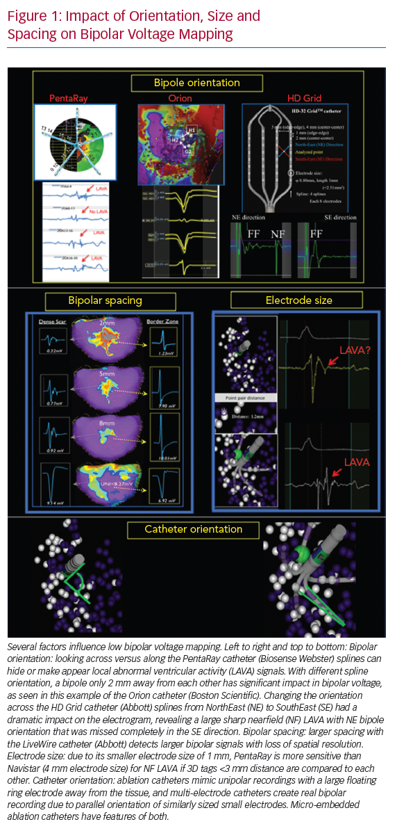
Several factors influence low BV mapping, such as tissue factors (e.g. healthy or fibrotic tissue and epicardial or myocardial fat), the influence of conduction velocity, fibre orientation and curvature, catheter–tissue relationship (angle of incidence, contact force, orientation in relation to wavefront propagation and tissue oedema), different filter settings and catheter characteristics (Figure 1).12 This review focuses on the impact of catheter characteristics, which include electrode size, shape and interelectrode spacing, and electrochemical factors, such as fractal surfacing, coating and welling.
Catheter Types and Configurations
Substrate mapping can be performed using conventional ablation catheters with a large tip, or using dedicated linear, basket, multi-spline or grid catheters. Recently, novel ablation catheters have been developed with mini- or micro-electrodes embedded in the distal tip electrode. Catheter and electrode design will influence:
- the amplitude and duration of the local EGM, and therefore, the spatial and temporal resolution of the catheter used;
- the field of view;
- the signal-to-noise ratio;
- the catheter-specific voltage values;
- the affinity to detect conduction channels and LAVA; and
- mapping density, and therefore, the efficiency of the catheter used.
Impact of Catheter Characteristics
Electrode Size and Catheter Orientation
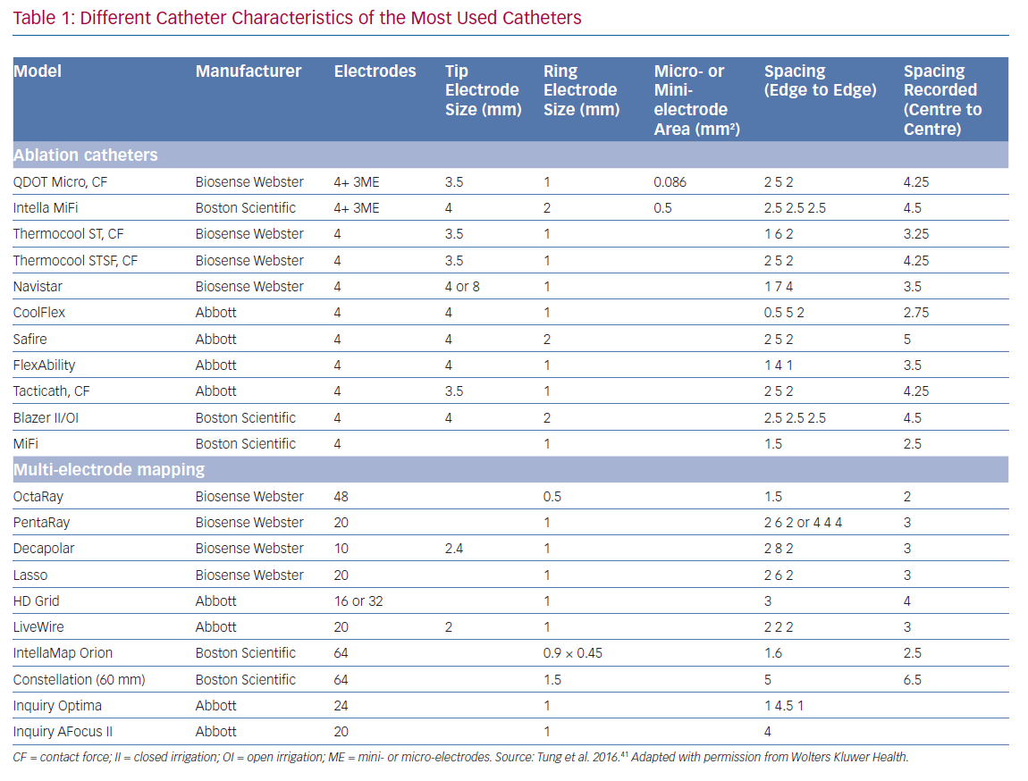
Smaller electrodes typically result in sharper (high frequency) and shorter EGM duration. The amplitude of a bipolar electrogram depends on the electrode size, the angle of incidence between the catheter and tissue, and the orientation of the bipole relative to the wavefront propagation. Standard 3.5-mm ablation catheters with larger tip electrodes and wide bipolar spacing can appear more similar to unipolar recordings, depending on the angle of incidence and the distance from the ring electrode to the tissue (Figure 1). The design of most multi-electrode catheters with small electrodes allows for a stable bipolar electrode position parallel to the tissue, thereby reducing the influence of the angle of incidence. Ablation catheters with incorporated micro-electrodes have features of both (Table 1).12 Bipolar voltage (BV) recorded with micro-electrodes are three times larger than BV recorded with conventional electrodes at the same site,17 but similar mean BVs were recorded using OctaRay versus PentaRay.17,18 Computing models and animal data suggest possible limited resolution differences <1 mm of electrode sizes for all catheter types.18,19
Interelectrode Distance
Increased interelectrode distance results in a larger BV amplitude and a loss of spatial resolution to detect LAVA.12,20,21 Both far-field and near-field BVs increase with increased spacing, although near-field increases may be less proportional. The near-field to far-field ratio increases due to predominant far-field rejection with closer spacing. Therefore, smaller spacing, ideally 1–2 mm, results in more optimal resolution. Only very small electrode sizes can be used in tight spacing (<1 mm) to overcome auto-cancellation within a bipole (Table 1).
Bipole Orientation
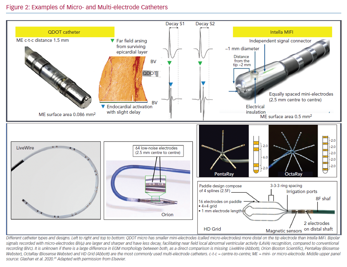
Multi-electrode catheters are highly dependent on the direction of the propagating wavefront relative to the orientation of the bipole pair (Figure 2).12 Depending on the spline orientation or different conduction (sinus rhythm or pacing manoeuvres), different BVs (variation around 30%) are measured, and a significant percentage of around 30% of LAVA are recorded or masked.7,21–23 These variations are most often present in the scar border zone (mixed scar tissue) and with orthogonal bipole activation. This limitation may theoretically be overcome using omnipole mapping or maximal bipolar amplitude mapping (HD wave) with the HD Grid catheter, or by concomitant use of imaging-derived substrate information.14,24 In theory, an incident wavefront that is exactly 90° to both bipoles would result in cancellation. However, in vivo, activation occurs in 3D, and it is unlikely that this scenario is relevant in clinical cases (isoelectric EGM without an intrinsic amplitude).25 Additionally, repeated sampling in a region of interest also overcomes this limitation, as the catheter orientation varies with each manipulation, increasing the probability of detecting a larger local EGM.
Customising Voltage Mapping Values Relative to the Recording Catheter
Conventional scar and low BV thresholds (0.5–1.5 mV) were defined by Marschlinski et al., based on mapping with a conventional large-tip electrode.1 The 1.5 mV threshold has been validated in animal models of transmural myocardial infarcts, but the dense scar level of 0.5 mV has been arbitrarily defined.26 Based on the prior findings and comparison with MRI-derived substrate, several authors have suggested specific BV thresholds for each dedicated mapping catheter:
- PentaRay: 0.2–1 mV or 1.5 mV;
- Orion: 0.1–1 mV
- LiveWire: 0.5–1.5 mV; and
- ablation catheter: 0.5–1.5 mV.20,27,28
As voltage thresholds have only been validated for post-infarct scars, the use of one single threshold is oversimplified. Due to the explanations above, it is likely that, for catheters with smaller electrode sizes and spacings, higher voltage thresholds to identify normal myocardium should be applied. For QDOT MICRO, scar thresholds of unipolar <5.44 mV, bipolar <1.27 mV and mini- or micro-electrodes (MEs) <2.84 mV have been suggested validated by histology in an animal infarct model.29 Whole-heart histology in non-ischaemic cardiomyopathy has highlighted that no specific cutoffs can be found, as fibrosis patterns and architecture are different compared with ischaemic cardiomyopathy, and wall thinning is often absent.30
Catheter Design and Configurations
Multi-electrode Catheters
Different models of dedicated multi-electrode mapping catheters are used: linear versus multi-spline versus grid versus basket catheters with around 0.5–1 mm3 electrode sizes and 2–3 mm interelectrode distances. With all currently available multi-electrode catheters, there is lack of contact force measurement, and the direction of the wavefront influences both electrogram amplitude and duration. Due to their location on the catheter tip (angle between the three bipoles is 60°), ME may at least partly compensate for wavefront influence, as the highest BV is recorded. In recent animal work, the highest recorded ME BV was was able to more adequately detect viable myocardium throughout the ventricular wall in an animal model of reperfused MI, validated by histology, compared to both conventional QDOT MICRO ablation electrodes and PentaRay.31
A custom-made 112-electrode (2 mm size, 1 mm spacing) endocardial balloon was used by another group to analyse extremely low amplitude potentials in the range of 50–100 μV. They found that decremental evoked potentials (using extra-stimulus testing) were more specific than LAVA potentials to identify the diastolic isthmus during ventricular tachycardia.32
Multi-spline variants of multi-electrode catheters are often arrhythmogenic during endocardial mapping, especially in small and healthy ventricles, and cannot correct for wavefront dependency of voltage, which can be achieved with a grid design. In theory, more accurate entrainment mapping can be performed using multi-electrode catheters due to less output required to capture from small electrodes and sharper EGM recording allowing for more precise measurements of local activation times. The ideal number, spacing and size of the electrodes of such catheters is still under investigation; for example, OctaRay mapping is faster and denser compared to PentaRay mapping, but has similar substrate resolution in a ventricular mapping study (Figure 2).
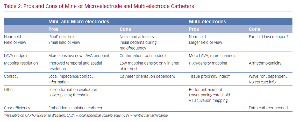
In the present study we hypothesised a ‘mapping plateau’ with electrode sizes <1 mm, which has been supported by a computational study comparing electrode sizes.18,19 More electrodes can increase mapping speed and density, and smaller sizes and spacing increase spatial resolution and potentially reduce RF time, but their additional impact on ventricular tachycardia non-inducibility or effectiveness is not known.33,34 Their (cost-)efficiency is questionable; although substrate maps can be acquired faster with higher density and better mapping resolution, a separate ablation catheter is still needed (Table 2).35
Mini- and Micro-electrode Catheters
There are currently two ablation catheters with smaller embedded electrodes: IntellaNav MIFI (without contact force, Boston Scientific) and QDOT MICRO (with contact force, Biosense Webster). The three micro-electrodes of the QDOT MICRO are smaller, more distally on the distal electrode located at a 60° angle compared to the three mini-electrodes of the IntellaNav MIFI that are slightly larger, and more proximally located on the electrode at a 90° angle (Table 1 and Figure 2). It is not known if the differences between both have a significant clinical impact. The highest ME BV is depicted to compensate, at least in part, for wavefront influence. Due to their design, they record sharper high-frequency EGMs and higher BVs (Figure 2). Therefore, different voltage thresholds for ME voltage maps are needed. These catheters may be more cost-efficient, as the mapping and ablation features are integrated, but mapping time is likely to be longer. These micro-electrode-embedded catheters could be used to directly check LAVA elimination, without the need for remapping with a multi-electrode mapping catheter, saving time and/or the need for an additional catheter.
The catheters can be used as standalone, but can also be combined with multi-electrode catheters or imaging-derived scar information (Table 2).36
Using only ME with a smaller field of view may also present disadvantages with regard to the durability of ablation lesions. In a recent study, radiofrequency applications were immediately terminated just after the rapid (4 seconds) loss of pulmonary vein signals on ME during pulmonary vein isolation. Of importance, reappearance of these micro-EGM signals was observed after 45 minutes’ waiting time, due to reversible oedema. Therefore, micro-EGM can be used to improve the ablation location accuracy, but should not be used to guide ablation duration.
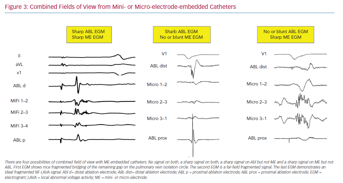
Differences in Fields of View
In a computational model, approximately 90% of the BV amplitude reflects the activation of the closest 1-mm myocardium. Accordingly, voltage mapping data for transmural tissue information need to be interpreted with caution.18 Successful ablation and termination of ventricular tachycardia is sometimes performed in locations without any signal on the distal bipolar EGM of the ablation electrode. The new ablation catheters mentioned above combine two different fields of view (Figure 3). This could lead to more detailed analysis of the subendocardially located tissue in contact using ME combined with a deeper analysis within the myocardial wall using conventional electrodes. In a recently published animal study, the accuracy in correctly identifying the histological substrate increased to 93% using ME in combination with conventional unipolar voltage mapping when using the QDOT MICRO catheter.17
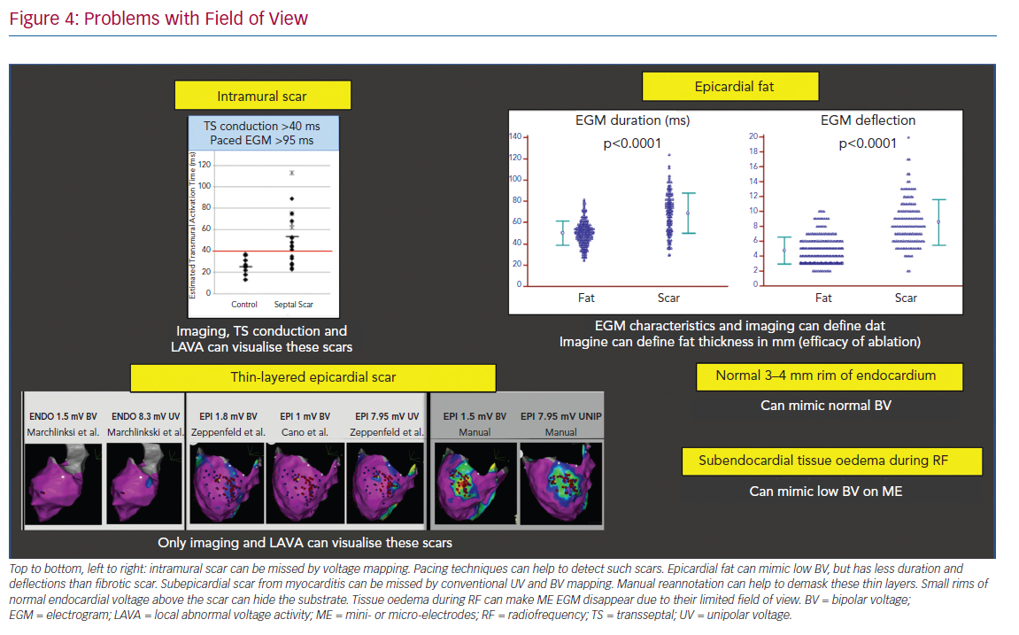
Specific problems concerning the field of view include:
- The detection of intramural scar covered by layers of viable myocardium may be detected by pacing manoeuvres measuring transseptal conduction time >40 ms and EGM duration >95 ms.37
- Epicardial fat mimicking scar due to attenuation of voltage, but with often shorter EGM duration and less deflections compared to scar.38
- Loss of micro-EGM on ME due to oedema can be interpreted in the same way.
- Thin-layered epicardial scar obscured by the underlying viable myocardium.39 Contrast-enhanced cardiovascular magnetic resonance can be helpful to identify intramural scars, and multi-detector CT can provide detailed information on epicardial fat thickness allowing for better interpretation of the local EGM amplitude (Figure 4).40
Difference in Signal-to-noise Ratio
Flat electrodes are less influenced by far field than cylindric or thicker electrodes, as they collect information further away from the tissue in contact. Fractal surface modification of the electrodes is sometimes used to obtain a small geometric footprint to minimise artefact interaction with multiple wavefronts. However, these fractals have high-electrode-tissue impedance, which increases the coupling of electromagnetic noise sources. Therefore, surface enhancements (e.g. Orion catheter with iridium oxide coating) can be used to decrease electrode-tissue impedance by dramatically increasing the active micro-surface area. By design, micro-electrodes have an excellent signal-to-noise ratio, if lab conditions are optimal.
Even with these enhancements, inherent noise and artefacts may be seen using micro- and mini-electrode mapping. Operator experience is required to recognise the spectrum of artefacts (artefacts from valves, papillary muscles, catheter movement or poor contact), filter setting dependency, irrigation before and during ablation and electrochemical dirt on the electrodes, and potential solutions to improve signal quality (e.g. high-output pacing through the recording electrodes). Improved tissue contact increases the impedance and improves the signal quality.
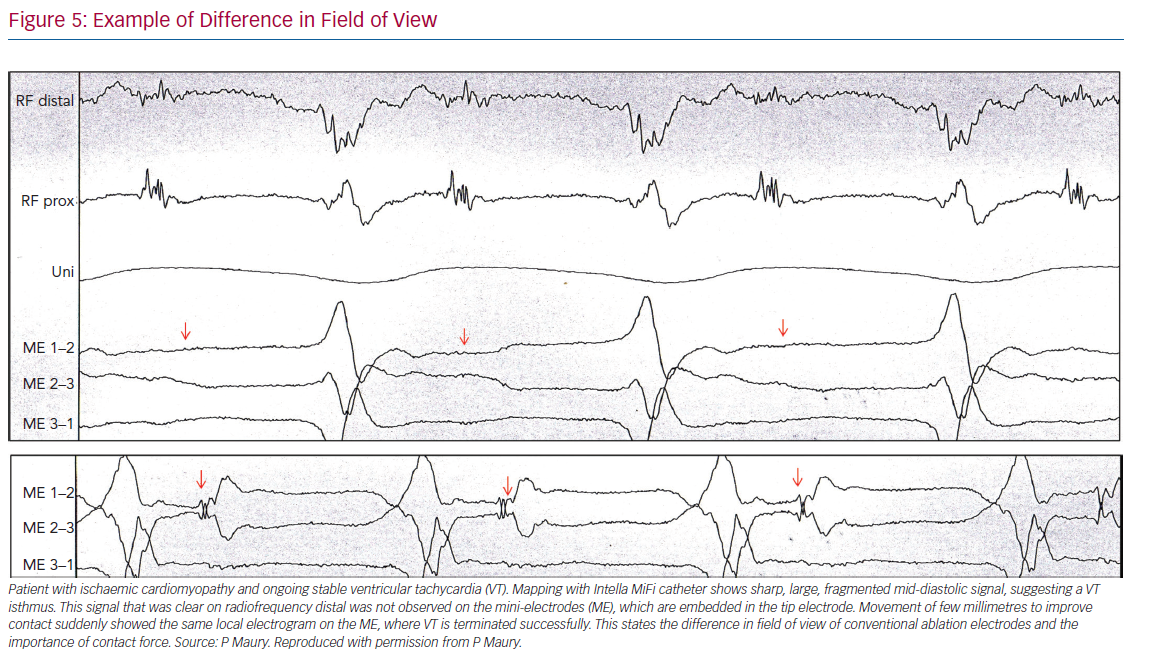
Distinguishing Near Field from Far Field
While it is important to distinguish near field from far field, a clear uniform definition is not available. In case of poorly coupled electrograms, the two or more components may all arise from near-field activation (double near field). With higher mapping resolution and limited field of view, greater detection and recording of near-field activity results. ME often generate sharper, larger signals with both higher spatial and temporal resolution compared with conventional electrodes. This can help to detect thin layers of viable myocardium.7 Examples of differences in field of view are given in Figure 5.
Comparing Catheters
Due to all of the abovementioned factors, it is important to understand the influence of the catheter design and the catheter–tissue interaction, and not only focus on single aspects, such as electrode size or interelectrode spacing. Bipole and catheter orientation, different filter settings, catheter noise, contact and contact force feedback contribute to EGM recordings. Therefore, operators should be familiar with the specific details of the catheter in use, including number of electrodes, electrode sizes, spacings and noise levels to understand the catheter-specific pitfalls. Table 1 summarises the important variations across diagnostic and ablation catheter configurations that influence the determination of voltage thresholds and the ability to detect near-field electrical recordings.
Conclusion
To understand substrate characterisation using specific catheters, knowledge of the impact of catheter design, bipole configurations and recording methods is critical. All electrograms recorded within a given substrate are subject to the size, spacing and orientation of recording electrodes relative to the wavefront. However, a gold standard does not currently exist. Increasing sampling density with smaller electrodes allows for higher resolution with a greater likelihood to record near-field electrical information, which has been demonstrated to be useful during sinus rhythm and ventricular tachycardia. These advances may help to further improve our mechanistic understanding of the correlation between substrate and ventricular tachycardia, as well as the characteristics of human re-entry.
Clinical Perspective
- Physicians should be aware of fundamental misconceptions about voltage mapping and the impact of various electrode sizes and configurations on electro-anatomical mapping.
- Catheter-specific voltage values should be used for accurate substrate detection and depiction.
- The use of conventional ablation catheters without additional imaging techniques or mapping electrode information is often insufficient for substrate recognition.