


Since the introduction of electroanatomical mapping (EAM) into clinical practice in 1997, remarkable progress has been made in catheter infrastructure, signal recording and processing, catheter guidance and visualisation and simultaneous real-time depiction and processing of different types of critical information during an ablation procedure.1 The latter, along with the comprehension of the pathophysiological mechanisms of arrhythmias’ induction and perpetuation have boosted catheter-based ablation of complex arrhythmias, such as atrial fibrillation (AF) and ventricular tachyarrhythmias (VAs). In this context, identification and modification of the arrhythmogenic substrate has entered clinical practice, leading, however, to elongated procedure times and increased exposure to ionising radiation for both operator and patients.
Contemporary three-dimensional (3D) EAM systems (EAMS) have significantly reduced the need for fluoroscopic visualisation of catheters.2,3 They have also created a precise and trustworthy ‘virtual environment’ capable of guiding complex mapping and ablation procedures. The latter is enhanced by integrating data from other imaging modalities, such as computed tomography (CT) and cardiac magnetic resonance (CMR). Contact-based EAM remains the standard of care in most cases, while non-contact and/or multipolar catheters enable high-density mapping of arrhythmias in as few as a single beat. Recently, the matter of optimal catheter–tissue contact and its effect on obtained data and ablation efficacy has been addressed by a number of studies.4,5 Modern EAM techniques have also been enriched with high-density body surface electrocardiogram (ECG) maps projected onto reconstructed images of cardiac chambers created by CT and CMR, in an attempt to map arrhythmias in a non-invasive way. In this review, the authors aim to sum up state-of-the-art EAM techniques and their impact on the acute- and long-term results of ablation of complex arrhythmias.
Clinical Perspective
- Electroanatomical mapping systems are the cornerstone of contemporary invasive cardiac electrophysiology.
- Identification and modification of the underlying arrhythmogenic substrate has emerged as an ablation strategy that improves outcome in atrial fibrillation and ventricular tachycardia ablation procedures.
- Implementation of contact force, image integration and hybridisation of existing electroanatomical mapping technologies are the necessary steps forward to further improve our effectiveness during mapping and ablation of complex arrhythmias.
Electroanatomical Mapping Systems’ Architecture and Features
Contact-based Electroanatomical Mapping
The two most widely used contact-based EAMS worldwide are CARTO® (Biosense Webster Inc., Diamond Bar, CA, USA) and EnSite NavX Velocity® (St Jude Medical, St Paul, MN, US). The primary inherent feature of every EAMS is considered the non-fluoroscopical and precise spatiotemporal depiction of various diagnostic and therapeutic catheters and devices into a 3D shell that reenacts the cardiac chamber of interest. This 3D shell consists of ‘electrical points’ sampled by the mapping catheter through contact with the anatomical structure. Modern EAMS incorporate utilities enabling computer-automated multi-point model creation while the mapping catheter is roved around the anatomical structure (CARTO3® Fast Map Module and EnSite NavX Velocity® One-Model Module).
The CARTO system is based on three active weak magnetic fields (5x10⁻⁶ to 5x10⁻⁵ Tesla), produced by a three-coil location pad placed underneath the patient’s thorax. Dedicated catheter tips incorporate a magnetic mini-sensor that continually measures the strength of the magnetic field and calculates the catheter’s exact position in space.1 Contemporary CARTO versions (CARTO3) can concurrently portray multiple catheters, due to a sophisticated current-based catheter location technology. Six electrode patches positioned at the patient’s back and chest monitor the current emitted at a unique frequency by various catheter electrodes.6,7 Visualisation of catheters is confined into a 3D virtual area called the ‘matrix’, which can be built only by a magnetic sensor-equipped manufacturer-specific catheter.
Ensite NavX technology in its latest version (Velocity) uses six skin electrodes to create a high-frequency electric field (8.0 kHz) in three mutually orthogonal planes on the patient’s thorax, creating a coordination system in three X/Y/Z axes. The 3D-localisation of conventional electrophysiology catheters is based on an impedance gradient-calculation system in relation to a reference electrode placed on the patient’s body, too.8 Field scaling is a process by which through complex calculations the body’s non-linear impedance can be overcome and a more representative model of the mapped 3D anatomy can be built.7,8 NavX Velocity is an architecturally open system within which multiple catheters from different manufacturers can be visualised.9 An additional advantage of the NavX Velocity technology during ablation procedures is that it is partially insensitive to potential patient movements, as the reference electrodes and catheters are placed either on the patient’s skin or in the patient’s cardiac chambers, respectively, and therefore they move simultaneously with the patient, preventing map shifts.
Recently, a novel EAMS (Rhythmia Mapping®, Rhythmia Medical, Boston Scientific Inc., Marlborough, MA, US) received regulatory approval. A major advantage of the new system is its ability to simultaneously record large numbers of electrograms (EGMs) with a very high spatial resolution. This is achieved through a specially designed mini basket bidirectional deflectable catheter (64-electrode IntellaMap Orion® High Resolution Mapping Catheter, Boston Scientific Inc.) The mapping catheter incorporates a basket electrode array (usual mapping diameter 18 mm) with eight splines. Each spline incorporates eight small, low impedance electrodes (64 electrodes in total). Electrode localisation is carried out by a magnetic sensor in the distal region of the catheter combined with impedance sensing on each of the 64 basket electrodes. Mapping in auto mode enables automatic annotation of activation times in sites of interest without manual interventions. The features and capabilities of this novel EAMS have been evaluated in canines by Nakagawa et al.10 A median of 4,227 EGMs with a median resolution of 2.6 mm in 6.1 minutes were obtained, enabling the rapid creation of a credible activation map.10 Clinical studies will clarify the potential value of the system in humans.
Contact Force
During an electrophysiological study, bipolar EGMs are the most commonly analysed waveforms. EGM properties that are usually used to draw conclusions on cardiac tissue characteristics include signal amplitude, power spectrum and fractionation.11–13 However, the distance and the orientation of the mapping catheter bipole to the underlying tissue plays a significant role in the qualitative and quantitative characteristics of the acquired signal, which, in turn, influence the results of voltage-based substrate mapping.14 Adequate contact between catheter and tissue is considered determinant to credible characterisation of the underlying arrhythmogenic substrate.15 Furthermore, even though lesion formation during ablation is evaluated through fulfilment of certain criteria, including EGM amplitude reduction, initial impedance and impedance drop during ablation and electrode temperature, the proper contact between tissue and catheter can be guaranteed only through its direct measurement. The contact force (CF) is used to evaluate the contact between the tissue and the catheter tip. Numerous studies have demonstrated that adequate CF is crucial for radiofrequency lesion size.16–20 At the other side of the CF spectrum, it has been found that lesions placed using high power settings (45 W) and high pressures (>40 g) are correlated to char and crater formation.21 Of note, CF <100 g during ablation procedures is associated with complications, i.e. cardiac perforation.5
Three available technologies enable direct measurement of CF during ablation procedures. The TactiCath® catheter (Endosense, Geneva, Switzerland) incorporates a force sensor between the second and third electrode, consisting of a deformable body and three optical fibres (0.125 mm diameter) to measure micro-deformations that correlate with the force applied to the catheter tip. Infrared laser light is emitted through the proximal end of the three optical fibres. The change of wavelength during application of CF to the tip of the catheter is proportional to the CF applied to the tip.4 The technology used in the ThermoCool SmartTouch® ablation catheter (Biosense Webster Inc., Diamond Bar, CA, US) is based on the electromagnetic location technology used in the CARTO3 System. The catheter tip electrode is mounted on a precision spring that permits a small amount of electrode deflection. A transmitter coil that is coupled to the tip electrode, distal to the spring, emits a location reference signal. Location sensor coils placed at the proximal end of the spring detect micro-movement of the transmitter coil, representing movement of the tip electrode on the spring. The system senses the location information of the sensor and calculates the associated force based on the known spring characteristics.22 The third system, IntelliSense® (Hansen Medical Inc., Mount View, CA, US), can be used in conjunction with the use of a dedicated robot system for catheter ablation.23
Non-contact and Multi-electrode Mapping
In contact-based EAMS, manual point-by-point mapping is required to build a proper activation map of the arrhythmia of interest, i.e. running tachycardia or extra-systoles. On the other hand, if the arrhythmia is not sustained or not haemodynamically tolerated, point-by-point mapping may be insufficient or even not feasible. Non-contact mapping can address this concern as it can create a full map even from a single tachycardia beat. The most widely applied non-contact mapping system uses the Ensite Array® (St. Jude Medical Inc., St Paul, MN, US) basketcatheter and requires a 3D Ensite NavX reconstruction created with a roving mapping catheter to project data on. The multipolar non-contact catheter uses 64 unipolar electrodes, which record virtual unipolar farfield EGMs using a mathematical inverse solution of the Laplace law and then project them (n=3,360) on an already reconstructed 3D model shell. The precision of the recorded EGMs depends on the distance from the centre of the array to the endocardial surface (R-value, displayed continuously during mapping) with distances <40 mm giving the most accurate data.24,25 Unipolar recording analysis is used after collection of data to build maps of interest.26 The specific shape of the basket catheter enables simultaneous recording of several potential sites of interest without actual catheter manipulation. During ectopic activity, virtual unipolar EGMs obtained at the earliest site of activation have a QS or rS morphology, with the intrinsic defection inscribing earlier compared with every adjacent sites.26 The variable distance and orientation of the centre of the EnSite balloon electrode to the recording sites can result in differing dV/dt of the virtual unipolar EGMs at different recording sites.26
During mapping in atria and in the right ventricle (RV), the basketcatheter remains constantly stable. However, quality of recorded signals worsens with distances exceeding 40mm from the centre of the array. In case of ventricular tachycardias (VTs) coming from the left ventricle (LV), the stability of the basket-catheter remains an important issue to be addressed. In the era of cost-effectiveness, another main drawback of non-contact mapping is the relatively high cost in comparison to conventional contact-based EAM.
Use of multi-electrode catheters enables rapid high-density activationand substrate-mapping through simultaneous multiple-point acquisition. Recently, a number of multi-electrode contact-based catheters (PentaRay®, Biosense Webster, Inc., Diamond Bar, CA, US) and the Duo-decapolar® catheter (Livewire®, 2-2-2 mm spacing, St Jude Medical, St Paul, MN, US) have been introduced into clinical practice. Using the PentaRay® catheter for the mapping of local abnormal ventricular activities in 35 patients with scar-related VT, Jaïs et al. found that the PentaRay® was capable of providing high-density maps with clean electrical signals, but also enabling careful monitoring of transmural response to ablation, which is particularly helpful in the case of high-density epicardial mapping.27 Several recent studies also showed promising applications of multi-electrode catheters.28,29 Della Bella et al. performed ultra-high-density mapping using the Duo-decapolar catheter to define features of complex post-infarction scar architecture by mapping of late potentials (LPs) that were critically related to reentrant VTs.30 Pacingmapping manoeuvres were also facilitated by the presence of multiple electrode pairs for pacing. A multi-electrode mapping strategy has the potential to further shorten procedural and fluoroscopy times. Prospective large-scale studies are warranted to establish the implementation of multi-electrode mapping in VT ablation.
Non-invasive Mapping
Non-invasive cardiac mapping provides information on the topography of arrhythmogenic foci pre-procedurally, in order to reduce timeconsuming mapping times. Body surface unipolar recordings are projected onto 3D reconstructed images of the heart derived from CT or CMR scans. Using complex mathematical equations, the torso potentials are related to the epicardial surface of the heart.31 Using body surface potential maps (BSPM) Lai et al. demonstrated the feasibility of this technique for approximating the site of origin of cardiac ectopic activity, propagation properties of ectopic beats and, most recently, for reporting on the value of BSMP-derived ventricular endocardial reconstruction for localisation of ventricular ectopic beats.32,33

Non-invasive mapping has strengthened efforts to explain the mechanisms involved to the initiation and perpetuation of AF. Haissaguerre et al. applied non-invasive electrocardiographic mapping in patients with AF and suggested a co-existence of multiple AF mechanisms, including wave genesis from focal sources or rotors, as well as wave propagation. Regarding rotors, their presence was not confined to a certain small area as they shifted to different areas of the atrium, recurring and firing occasionally.34
Implementation of Electroanatomical Mapping Systems in Clinical Practice
Ablation of Atrial Fibrillation
Contact-based EAMS are ideal for visualising reentry circuits or centrifugal activation round an arrhythmogenic focus in 3D reconstruction models. As a result, EAMS are of utmost importance in AF ablation procedures and in macroreentry, focal or microreentry atrial tachycardias (ATs) outside PVs, during index or repeat procedures.11,35–38 Non-contact mapping is not consistently used for catheter ablation of AF, although it may facilitate recognition of gaps in the ablation lesions in redo procedures and localisation of arrhythmogenic extra-PV foci.26,39 Entrainment techniques can be applied during mapping of macroreentry ATs with stable cycle length. Using colour-coded 3D entrainment with the help of EAMS Esato et al. precisely portrayed the 3D location of the reentrant circuit in all 26 patients with regular macroreentry AT enrolled in the study. Lines of impulse propagation were interrupted by linear lesions, resulting in a procedural success of 100 %. Of note, 88 % of patients had no AT recurrences during follow-up.40
Substrate Modification
EAMS depict voltage maps on 3D reconstruction models. In the atrium, areas with endocardial bipolar voltage amplitude of <0.5 milli-Volt (mV), ≤0.5–1.5mV≤ and >1.5 mV are considered dense scar, border-zone and healthy tissue, respectively. Low-voltage is considered a surrogate of atrial fibrosis, although cut-off scar values for scar identification were originally based on baseline noise level recorded in early EAMS (see Figure 1).41 Only recently, a validation study using CMR endocardial voltage mapping and histological examination of post-ablation injuries in pigs, demonstrated a mean voltage amplitude at the centre of the ablation line of 0.6 mV immediately post-ablation, and 0.3 mV late after ablation.42 A bipolar voltage cut-off value of 0.2 mV (0.45 mV for the left pulmonary vein [PV]-left atrial appendage ridge) and 0.15 mV (0.2 mV for the left PV-left atrial appendage ridge) can identify acute and chronic inexcitable dense scar in patients undergoing first time PV isolation (PVI) and redo PVI, respectively.43 In patients undergoing AF ablation with PV antrum isolation, in whom existing low-voltage areas are not modified, the latter are independently related to AF recurrence during follow-up.44 Recently, the Delayed-Enhancement MRI Determinant of Successful Radiofrequency Catheter Ablation of Atrial Fibrillation (DECAAF) study demonstrated that increased atrial tissue fibrosis quantified by CMR with late gadolinium enhancement (LGE-CMR) was independently related to recurrence of AF following ablation procedure.45 Our group has recently demonstrated the presence of low-voltage areas by endocardial bipolar mapping in 35 % of patients with persistent AF and in 10 % of patients with paroxysmal AF. In patients without low-voltage areas no further substrate modification was performed. After a single procedure, 62 % of them remained free of atrial arrhythmias. By contrast, 23 % of patients with low-voltage areas and PVI only remained free of arrhythmia after 12 months of follow-up. In the group of patients with low-voltage areas and substrate-guided modification, a 70 % success rate of arrhythmiafree survival after one year was reported.46 Prospective randomised clinical studies evaluating the effects of ‘low-voltage areas’ ablation are warranted in order to further clarify the impact of substrate modification on post-procedural AF-free survival.
Contact Force
CF mapping is another piece of the puzzle in AF ablation procedures. It enables acquisition of voltage points without the restrictions of potential lack of contact and creation of credible maps of the underlying substrate. More importantly, efficient CF has been shown to be associated with the permanence of PVI. In the TOuCh+ for CATheter Ablation (TOCCATA) study, all patients with an average CFCF<10 g experienced recurrences, while 80% of the patients ablated with an average CF>20 gremained free of recurrence during 12 months follow-up.47 The Efficacy Study on Atrial Fibrillation Percutaneous Catheter Ablation With Contact Force Support (EFFICAS I) trial correlated the CF during the initial procedure and the incidence of isolation gaps at three months follow-up. Reconnection of the PVs correlated strongly with minimum CF and minimum forcetime integral (FTI, i.e. amount of contact applied over time) at the site of gap. CF and FTI were reported as higher on the right PVs. The authors recommended an optimal CF target of 20 g and a minimum FTI of 400 g x second (gs) for each point lesion.48 Patients achieving a mean CF >20 g require shorter procedural time, without significant difference in complication rate in comparison to patients in whom CF is <10 g.49 Recently, the transmurality of the ablation lesion has been correlated with CF and FTI. Squara et al. suggest that an FTI >392 gs can be used as an endpoint during radiofrequency ablation, which corresponds well to already published data.50
Complex Fractionated Atrial Electrograms
Complex fractionated atrial electrograms (CFAEs) are defined as low voltage (≤0.15 mV) multi-segment signals with one or both of the following characteristics: (1) atrial EGMs composed of two deflections or more and/or perturbations of the baseline with continuous deflection of a prolonged activation complex; (2) atrial EGMs with a very short cycle length (≤120 milliseconds), with or without multiple potentials.51 The exact role of CFAE in the pathogenesis of AF has not been yet clarified. CARTO® and NavX® integrate specific algorithms that enable acquisition of CFAEs and construction of corresponding maps. However, the number and allocation of CFAEs are rhythm dependent and in only 5 % of the patients a fractionation in both sinus rhythm (SR) and AF could be proved.52 In a recent meta-analysis, PVI alone was compared with PVI with additional CFAE ablation. The authors concluded on lower recurrence rates of atrial tachyarrhythmias after a single procedure when supplementary CFAE ablation was performed in cases of persistent and long-lasting persistent but not paroxysmal AF.53
Focal Impulse and Rotor Modulation Mapping and Ablation
The mechanisms perpetuating AF after initial onset are still only partially defined, with distinct theories having been developed over the years. Recently, in an effort to further elucidate this question, Allessie et al. performed epicardial wave mapping during heart surgery in patients with long-standing persistent AF and demonstrated the presence of multiple wavelets separated by lines of longitudinal conduction block propagating through the atrial wall.54 Rotor theory, along with demonstration of focal impulses, has nowadays emerged as an equally significant major cause for AF.55–57 Narayan et al. developed a novel computational contact mapping approach that involved the use of two 64-pole catheters (Constellation, Boston Scientific, MA, US) placed simultaneously in the left and right atrium, to collect and analyse monophasic action potential data during AF. Absolute electrode locations within the atria were visualised within the NavX® or CARTO® environments.58 Spatiotemporal analysis of AF was performed primarily by directly analysing EGMs. Large numbers of AF-activation cycles were then reconstructed as movies or isochronal maps to exemplify single cycle snapshots of AF. Rotors were identified as rotational activity around a centre (using isopotential movies and isochronal activation maps). Focal beats in AF were then identified at their point of origin based on isopotential movies and isochronal maps. Sustained localised electrical rotors and repetitive focal beat sources were identified in nearly all AF patients studied.58 The subsequent Conventional Ablation for Atrial Fibrillation With or Without Focal Impulse and Rotor Modulation (CONFIRM) study included 92 patients undergoing 107 ablation procedures, in which a conventional strategy during ablation was prospectively compared with ablation at sources followed by conventional ablation.59 With the use of a novel system (RhythmView, Topera Medical, Lexington, MA, US), computational maps of AF were generated. Rotors or focal impulses were observed in the majority (97 %) of cases. During focal impulse and rotor modulation (FIRM) ablation, the ablation catheter was manipulated within the area indicated by the FIRM map as the centre of rotation (for rotors) or focal impulse origins. The authors demonstrated that ablation of drivers in human AF, in the form of small number of stable rotors or focal sources, frequently located outside the PV ostia, was able to terminate or slow AF and improve AF ablation outcomes. In a recent sub-analysis of the CONFIRM trial, it was further shown that, in patients with obesity, hypertension, obstructive sleep apnoea (OSA) and enlarged left atria (>40 mm), FIRM mapping was able to identify more coexisting AF sources, distributed more extensively in both atria compared with patients without such comorbidities. Reported freedom from AF after a single procedure was significantly higher when FIRM ablation was used (>80 % versus <50 %).60
Ripple Mapping
Established EAMS necessitate manual-based annotation and/or evaluation of acquired map points because automated annotation has been so far prone to serious errors. On the other hand, manual point-by-point annotation can also lead to severe signal misjudgement. In an alternative assessment by Linton et al., EGM location, timing and amplitude were presented on the shell of the cardiac chamber created by CARTO XP® and EGMs were visualised as colour bars with corresponding 3D coordinates, of varying colours and dimensions according to the voltage–time relationship, time-gated to a preselected reference EGM. This gave the impression of a ‘wave-like’ movement of the propagation, without the need for any intervention to adjust the manual or automatic annotation.61 Recently, data on the feasibility of ‘ripple mapping’ for the diagnosis of atrial tachycardias were published.62
Ablation of Ventricular Tachycardia
Application of mapping strategies during VT ablation are constrained by a series of factors, including:
- The ability to reproducibly induce the clinical tachycardia
- The potential induction of multiple, eventually not clinically relevant VTs
- The haemodynamic tolerance of the induced tachycardia.
In haemodynamically tolerant ongoing reentry or mostly focal VTs, creation of an activation map is the ‘gold standard’ method for depicting reentry circuits or foci. Mapping can be performed using unipolar or bipolar recordings, non-contact mapping or multi-electrode arrays visualised on EAMS.30,63,64 During haemodynamically stable VTs, entrainment manoeuvres demonstrating concealed fusion of QRS complexes can indicate placement of the catheter on a critical VT isthmus – it is important to know that post-pacing intervals can reliably distinguish between critical isthmuses and bystander sites.30,65
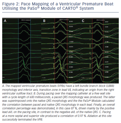
If the tachycardia of interest is not inducible, not sustained nor haemodynamically untolerated, the aforementioned mapping techniques are not easily applicable. Pacing over the ablation catheter can be performed and the resulting QRS complex is compared with that of the clinical and/or induced VT. Demonstration of a 12-lead QRS morphology resembling or optimally being identical to the VT morphology guides ablation at the pacing site of interest. de Chillou et al. assessed post-infarct critical isthmuses of reentry VTs and created colour-coded high-density 3D pace-mapping maps. The pace maps were matched to the 3D endocardial reentrant VT activation maps. The resulting paced 12-lead ECG at areas of interest was compared with that of the clinical VT and matched up to 100%. The subsequent sequences (from the best to the poorest matching sites) on the pace-mapping maps revealed figure-of-eight pictures in concordance with VT activation maps and identified critical VT isthmuses.66 Manual comparison of ECG configuration, however, can be time-consuming and subjective. Recently, a novel module of the CARTO® EAMS was introduced. The PaSo® module delivers automated template matching for targeting complex VT procedures (see Figure 2). It automatically compares pace mapping signals with arrhythmia signals to guide VT ablation.67,68 So far, however, no clinical studies have compared the PaSo® module with conventional pace mapping to evaluate procedure-, fluoroscopy- and application-time and efficacy rates.
Substrate Modification
In patients with cardiomyopathies, the majority of arising VTs are caused by reentry mechanisms. The reentry circuit is almost always defined within areas of low voltage and slow conduction. In ischaemic cardiomyopathy (ICM) distinct subendocardial or even transmural scar areas corresponding to the level and distribution of underlying coronary vessel disease are identified. Around areas of dense myocardial fibrosis, border zones contain irregularly arranged islets of surviving myocyte bundles that can act as pathways of slow conduction, giving rise to reentry VTs.69 In non-ischaemic dilated cardiomyopathy (NIDCM), areas of low voltage and slow conduction exist dominantly in the epicardial layers of the cardiac muscle, frequently sparing the endocardium. The distribution of fibrosis is rather unpredictable, although postero-lateral areas and regions bordering on valvular annuli are most often involved.70 Finally, in arrhythmogenic right ventricular cardiomyopathy/dysplasia (ARVC/D) areas of endocardial electroanatomical scar extend from the tricuspid or pulmonary valve to the RV free wall, while the RV apex seems to be excluded.71,72 Low-voltage epicardial areas correspond well to endocardial ones but extend further over the surface of the RV.73
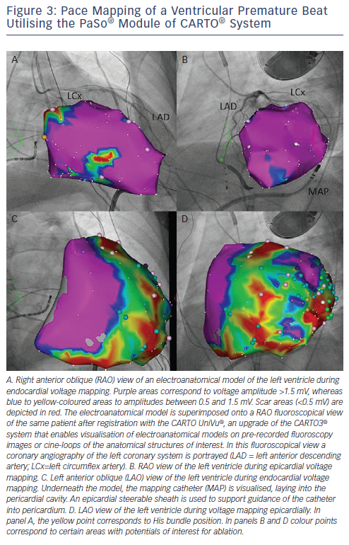
The identification and modification of the arrhythmogenic substrate in the endocardium and/or the epicardium is considered as primary ablation strategy in contemporary VT ablation procedures in patients with structural cardiomyopathies.74 Bipolar mapping is the gold standard technique to characterise substrate. Endocardially, a bipolar voltage amplitude of ≥1.5 mV identifies healthy tissue and areas with voltage of 0.5 to 1.5 mV are considered border zones. It is suggested that the majority of unstable VTs have critical circuit components located in the border zone.75 In the epicardium, a bipolar voltage cut-off of ≥1 mV is considered normal and voltage amplitudes of 0.5 to 1.0 mV define the border zone. ‘Scar’ is defined as an area with bipolar signal amplitude <0.5 mV both endo- and epi-cardially (see Figure 3).76 Unipolar endocardial voltage mapping offers a larger field of view to the operator, in particular it portrays information on the degree of epicardial presence of low-voltage areas. Unipolar voltage amplitude of ≤6.52 mV has shown optimal receiver operating characteristic curves for defining scar consistent with LGE-CMR and is suggestive of epicardial low-voltage areas.76 A variety of abnormal EGMs are recorded in areas of scar/low-voltage, i.e. fractionated potentials, double potentials and LPs (discrete and separated from QRS by 40 milliseconds (ms). These voltage criteria were recently validated in a myocardial viability study using fluoro-deoxyglucose positron-emission tomography (FDG-PET).77
A variety of methods are implemented during substrate modification, resulting in extensive or less-extensive ablation lesions according to the preset endpoints of the procedure.11,78–80 The main strategies include: i) linear ablation lesions with cross-section of the scar and border-zone, ii) scar/border-zone encircling, iii) placement of short lines after identification of the critical isthmus by entrainment or by pace mapping and additional lesions during SR, parallel to the border zone of the infarct until loss of capture during pacing at 10 milli-Ampere (mA) at 2 ms stimulus strength, iv) ablation of conducting channels and v) complete LP abolition.81 Since Marchlinski et al. demonstrated that linear lesions extending from the dense scar to the normal endocardium or anatomic boundary are effective in preventing recurrence of difficult-tomap VT, efforts have been made to limit the extent of ablation to critical parts of the reentry pathway, i.e. the reentry isthmus or transection, after identification, of conducting channels and delayed potentials.11,82,83
The presence of LPs may correlate with a better post-ablation outcome.84 Both patients with ischaemic and non-ischaemic VT seem to profit from an ablation strategy based on LP ablation.85,86 Vergara et al. reported a success rate of 71.4 %, as defined by VT non-inducibility in patients with inducible VT before the ablation. EAMS enabled the creation of colourcoded LP maps, which were compared with LP maps post-ablation. In patients with complete LP abolition, VT was inducible only in 16 %, demonstrating that complete LP was a significant predictor of VT-free survival.81 Ablation of LPs can also alter electrical activity in regions of scar outside of the known radius of a radiofrequency lesion, accelerating scar homogenisation without the need for abolition of all LPs.87 Beyond established criteria of successful VT ablation, Vergara et al. suggest LP abolition as an additional endpoint of the procedure.81 Of importance, though, is the timing of LPs in relation to the QRS as it is related to their localisation. Substrate-based mapping and ablation targeting LPs may oversee a proportion of the arrhythmogenic substrate, particularly in the septum and other early-to-activate regions.87 Prospective randomised studies should assess the relative efficacy of different ablation strategies regarding VT substrate modification.
In patients with coronary artery disease (CAD) and remote myocardial infarction, the feasibility and effectiveness of catheter ablation for the treatment of malignant VAs have been established.88,89 The recently published Heart Center of Leipzig VT (HELP-VT) study demonstrated an acute complete success of the procedure (non-inducibility of any clinical and non-clinical VT) in 77.4 % of patients with ICM in comparison with 66.7 % patients with NIDCM.90 Although there was no statistically significant difference in short-term outcome between the two groups, long-term outcome differed significantly in favour of ICM, with rates of freedom from VT of 57 % and 40.5 %, respectively.90 In the largest series of NIDCM VT patients so far, acute complete success of 51 % and partial success of 29 % were reported after combined endocardial/epicardial mapping and ablation. Epicardial mapping was performed only in case of a failed endocardial approach.91 In this context, if a significant substrate endocardially is absent and electrocardiographic criteria indicate an epicardial origin of the VT, a combined concomitant endocardial/epicardial approach is suggested, in order to improve outcome.92 Even in case of no suspected epicardial VTs, subxyphoidal puncture and placement of a guidewire in the epicardial space before endocardial mapping and administration of intravenous anticoagulation should be taken into consideration.92
The extent of bipolar but not unipolar RV endocardial low-voltage area was the only independent predictor of arrhythmic outcome in a series of 69 prospectively studied patients with ARVC/D, independent of history and RV dilatation/dysfunction. A normal bipolar voltage in the RV characterises a low-risk subgroup of ARVC/D patients.93 Bai et al. compared endocardium-confined ablation versus endocardial/ epicardial substrate-based ablation and reported a rate of freedom from any VT of 52.2 % and 84.6 %, respectively.94 Recent data confirm the superiority of epicardial ablation in this population. Out of 87 patients from 80 different centres who underwent epicardial ablation, 64 % and 45 % were free from VT recurrence at 1 year and 5 years follow-up, respectively, an outcome significantly better compared with endocardial-defined ablation.95 Tschabrunn et al. favour a step-by-step approach in such patients, suggesting endocardial substrate mapping in SR in the RV and subsequent epicardial mapping if VTs are inducible after endocardial ablation.96
Image Integration
In VT ablation procedures, additional information on the presence and distribution of myocardial substrate is needed. Scar image integration has recently been implemented in an effort to improve substrate identification and modification. Contrast-enhanced multi-detector CT images have been used in combination with electroanatomical maps to accurately identify dense scar and border-zone regions in 81.7 % of analysed segments.97 LGE-CMR is considered the gold standard in portraying and quantifying myocardial scar. Feasibility of LGECMR image integration into electroanatomical maps using different strategies of image registration has been already demonstrated.98–100
Integrated LV images depicting scar areas significantly improve the accuracy of endocardial or epicardial substrate mapping, particularly in areas where proper and sufficient catheter contact is difficult to achieve.98 In patients with an implanted cardioverter-defibrillator (ICD), LGE-CMR has also been proved feasible and safe, offering a significant amount of additional data on scar regions and facilitating scar identification and mapping.101 In this study by Dickfeld et al., 4 % of mapping points with initial voltages of <1.5 mV were found to have been caused by suboptimal catheter contact. Voltage >1.5 mV could result from 2 mm of viable endocardium, although mapping was conducted in an area of >63 % meso-myocardial scar. LGE-CMR integration enabled portrayal of mid-myocardial scar, which was not detected by conventional endocardial mapping.101 More recently, Piers et al. made significant headway in the optimisation of voltage cut-off points in the epicardium by performing EAM in patients with NIDCM with real-time integration of CT-derived epicardial fat and LGE-CMR.100
Contact Force
In a pivotal study, Mizuno et al. evaluated CF during VT ablation procedures.15 They suggested a CF cut-off value of 9, 8, and 8 g to obtain adequate systolic and diastolic contact in the RV, LV and epicardium, respectively. Application of the classic criteria to assess tissue contact led to a high number of points with poor contact, defined as absence of positive CF in diastole (50.9 %), revealing their limits on defining tissuecatheter contact. A weak CF <3 g led to low signal amplitudes. Increase of CF caused the increase of unipolar and bipolar signal amplitude followed by plateau when CF exceeded 20 g. The frequency of LPs identified in points with poor contact was significantly lower than that in points with good contact (11.9 % versus 23.2 %).15 The authors hypothesised that certain cut-offs for the various angles might be derived from analysis of the CF under intracardiac echocardiography monitoring. A potential reason for inferior CF values during the retrograde approach in comparison to transseptal one could be the requirement of two curves in the mapping catheter to reach the anterior and basal-septal walls of the LV.15 Tilz et al. recently conducted a direct comparison of antegrade versus retrograde LV-mapping approach and demonstrated that they result in different CF and suggested that a combined approach would result in better clinical outcomes after VT ablation.102
Non-contact Mapping in Ventricular Tachycardia Ablation
Non-contact mapping is applicable in VT mapping.103 Nair et al. reported on endocardial mapping and ablation of VTs in patients with ARVC/D. EnSite Array® enabled endocardial unipolar activation mapping of unstable VTs, even in a single beat.63 Zhang et al. reported on the feasibility of non-contact mapping in ablation of right outflow tract arrhythmias even though spatial resolution of activation and pace mapping is limited by rapid electrical propagation in the right ventricular outflow tract (RVOT). With a follow-up of 36.2±17.5 months, the success rate after a single procedure without antiarrhythmic agents was 86.8 %.104 Most recently, thorough analysis of virtual unipolar EGMs using non-contact mapping enabled the differentiation of left versus right-sided outflow tract foci while it has also the potential to guide ventricular extrasystole and/or VT ablation in this region.105
Arrhythmogenic substrate can be identified using the Dynamic Substrate Mapping® (DSM) module of the EnSite Velocity® system (St Jude Medical Inc., St Paul, MN, US).106 Voss et al. electroanatomically reconstructed LVs of sheep with a roved mapping catheter and applied DSM to define myocardial infarct size in comparison to CMR. They demonstrated a good correlation of scar to peak negative voltage amplitudes of <34 % of maximal unipolar noncontact EGMs recorded providing a static isopotential voltage map during SR.106 Visualisation of VT reentry circuit by non-contact mapping is feasible.107 Vergara et al. portrayed in vivo critical components of reentry circuit during the same beat during SR, ongoing VT and pace mapping.107 Prospective studies are cine qua non in order to define the usage spectrum of non-contact mapping in VT ablation.
Perspectives
The exciting journey of invasive electrophysiology continues with significant innovations entering and shaping the clinical practice. EAMS have come a long way in improving our understanding of diverse pathophysiological mechanisms that initiate and perpetuate arrhythmias, enabling real time visualisation of data that are essential to the operator and in applying of effective therapeutic solutions even for the most complex arrhythmogenic substrates. Credible visualisation of areas of low-voltage/scar surrogating fibrosis further impels our ability to effectively modulate/eliminate arrhythmogenic substrate and change the prognosis of patients suffering from highly symptomatic complex supraventricular and ventricular arrhythmias. Real-time feedback on tissue-catheter contact and multi-electrode high-resolution mapping with reliable automatic point annotation further augment our mapping armament. In fact, what we were imagining 20 years ago is now becoming true. Our primary future goal should be to improve effectiveness of mapping with the help of EAMS through hybridisation of technologies available, along with implementing state-of-the-art technology in as many electrophysiology labs worldwide as possible with rational cost.